Autonomous AP with Local RADIUS server – LEAP

Usually we use a external RADIUS server(ACS or ISE) for authentication in big enterprise but in small office it’s not feasible solution because of cost.

In this kind of situation, a standalone/autonomous AP can act as a RADIUS server. User are authenticate against the Local database configured in AP.

Autonomous AP can authenticate using LEAP, EAP-FAST and MAC based authentication.

In this post we will see, how to configure LEAP and local RADIUS server on AP.

To configure LOCAL RADIUS server on AP:

  1. IOS on AP must have at least 12.2(11)JA or higher version
  2. Remember LEAP is not strong method for authentication

Via CLI:

Switch config for AP connection:

int fa 0/15
  switchport mode trunk
  switchport trunk encapsulation dot1q
  switchport trunk allowed vlan 100, 101

Step1: Configure the SSID and map to a VLAN

Config t
 Dot11 ssid data1
 Vlan 101
 Authentication open eap local_eap
 Authentication network-eap local_eap
 Authentication key-management wpa version 1
 Guest-mode
 end

Step2: Configure the radio and Ethernet interface

Config t
 Interface dot11Radio0
 ssid data1
 exit
 !
 Interface dot11Radio0.100
 encapsulation dot1Q 100
 !
 Interface dot11Radio0.101
 encapsulation dot1Q 101
 bridge-group 101
 exit
 !
 int fa 0.100
 encapsulation dot1Q 100
 !
 int fa0.101
 encapsulation dot1Q 101
 bridge-group 101
 exit

Step3: Assign encryption to SSIDs with VLAN

Int dot11Radio0
 Encryption vlan 101 mode  ciphers tkip

Step4: Configure AP for management

Int BVI1
 Ip address 10.35.100.250 255.255.255.0
 !
 Ip default-gateway 10.35.100.254

Step5: Define a AAA group, AAA login method and configure RADIUS server with its own IP address

aaa new-model ->This command reinitializes the authentication, authorization and accounting functions.
aaa group server radius radius_leap
server 10.35.100.250 auth-port 1812 acct-port 1813  ->A server group for RADIUS is created called "rad_leap" that uses the server at 10.35.100.250 on ports 1812 and 1813.
aaa authentication login local_eap group radius_leap -> Authentication [user validation] is to be done for users in a group called "local_eap" who use server group "radius_leap".
aaa authentication exec default local

Step6: Configure local AP as authenticator

radius-server host 10.35.100.250 auth-port 1812 acct-port 1813 key leap12345 

Step7: Configure local users to authenticate as NAS entries.

Radius server local
 Nas 10.35.100.250 key leap12345
 User Sandeep password test12345
 User Sandeep1 password rscciew123

Step8: Verification with screenshot

leap_autonomous


ap#sh dot11 associations
 802.11 Client Stations on Dot11Radio0:
 SSID [data1] :
 MAC Address    IP address      Device        Name            Parent         State
 bd7b.a1d1.c289 10.35.101.252    ccx-client    ap              self           EAP-Assoc
ap#sh dot11 associations ac7b.a1d1.c289
 Address           : bd7b.a1d1.c289     Name             : ap
 IP Address        : 10.35.101.252       Interface        : Dot11Radio 0
 Device            : ccx-client         Software Version : NONE
 CCX Version       : 4                  Client MFP       : Off
 State             : EAP-Assoc          Parent           : self
 SSID              : data1
 VLAN              : 81
 Hops to Infra     : 1                  Association Id   : 1
 Clients Associated: 0                  Repeaters associated: 0
 Tunnel Address    : 0.0.0.0
 Key Mgmt type     : WPA                Encryption       : TKIP
 Current Rate      : 54.0               Capability       : WMM ShortHdr ShortSlot
 Supported Rates   : 1.0 2.0 5.5 11.0 6.0 9.0 12.0 18.0 24.0 36.0 48.0 54.0
 Voice Rates       : disabled           Bandwidth        : 20 MHz
 Signal Strength   : -37  dBm           Connected for    : 213 seconds
 Signal to Noise   : 58  dB            Activity Timeout : 50 seconds
 Power-save        : Off                Last Activity    : 0 seconds ago
 Apsd DE AC(s)     : BK BE VI VO
 Packets Input     : 910                Packets Output   : 175
 Bytes Input       : 130156             Bytes Output     : 69771
 Duplicates Rcvd   : 0                  Data Retries     : 35
 Decrypt Failed    : 0                  RTS Retries      : 12
 MIC Failed        : 0                  MIC Missing      : 0
 Packets Redirected: 0                  Redirect Filtered: 0
 Session timeout   : 0 seconds
 Reauthenticate in : never

Upgrade IOS on Cisco autonomous AP

In this post we will see the software upgrade on Autonomous AP.

Normally upgrade is performed in order to take advantage of the new features or if there bug in old IOS or this is the standard from company side to upgrade to the latest version of IOS on AP…there can be many reason to up-gradation.

IOS upgrade on standalone AP can be done by two ways:

  • GUI
  • CLI

Via CLI:

Step1: Download a new IOS image from cisco.com for respective AP model.

Step2: Open TFTP server on a notebook.

Step3: Put this new image on TFTP root directory.

Step4: Here come two things:

      1. Do you want to overwrite the old image?
      2. Do you want to keep the old image and also want to install new one. ?

Step5: Let’s say: we want to overwrite the old IOS, then we must use this command:

 AP#archive download-sw /overwrite /reload tftp://location/image-name

overwrite option overwrites the software image in flash with the downloaded image.

reload option reloads the system after you download the image unless the configuration is changed and not saved.

 location, specify the IP address of the TFTP server.

image name, specify the Cisco IOS filename that you plan to use to upgrade the access point

Step6: Let’s say: We want to keep the old IOS and install the new one on AP, then issue this command:

AP#archive download-sw /leave-old-sw /reload tftp://location/image-name

*** If there not so much space then in between download process a error message will be displayed and it will stop the download.
Step7: After download a new IOS, AP will reload or you have to manually reload the AP.

Step8: Verify with show version command about the new software version.

Via GUI:

Step1: Download the new IOS from cisco.com by your CCO id.

Step2: Open TFTP server and put the new image in TFTP root directory.

Step3: Login to AP GUI, click on the System Software menu from the left hand side. Choose the Software Upgrade option. (On this page we can see the present system software version)

Step4: From the software upgrade page, choose TFTP upgrade.

Step5: Enter the IP of TFTP server and the image name.

Step6: Click upgrade.


Unicast, Broadcast and Multicast

Earlier I was so confused with these terms..may be many of others have same problems like me or may be not.

Here I tried to explain in simple way(Also copied many things from internet to make it simple and easy to understand. )

Unicast

Unicast packets are sent from host to host. The communication is from a single host to another single host. There is one device transmitting a message destined for one receiver. In another words, Unicast transmission is between one-to-one nodes (involving two nodes only).

Examples of Unicast transmission are http, smtp, telnet, ssh, pop3 where the request for information is directed from one sender to only one receiver at the other end.

To understand this better, try to imagine a scenario where one computer’s request for the URL(google.com) is received by every other computer that’s connected to the Internet. This way Internet will be flooded with such requests and therefore there is a strong need for Unicast transmission on small and large networks. All Ethernet and IP networks support this type of transmission.

Unicast uses TCP for its communication and packet transmission.

Broadcast

Broadcast is when a single device is transmitting a message to all other devices in a given address range. This broadcast could reach all hosts on the subnet, all subnets, or all hosts on all subnets. Broadcast packets have the host (and/or subnet) portion of the address set to all ones. By design, most modern routers will block IP broadcast traffic and restrict it to the local subnet.

In other words, broadcast is a type of transmission in which information is sent from just one computer but is received by all the computers connected to the network. This would mean that every time a computer or a node would transmit a packet of type ‘broadcast’, all the other computers will receive that information packet.

Examples of broadcast are many but one that would be best to understand here is a computer booting up and requesting for a IP address. In this case, the computer which is booting up and requesting for an IP address does not know which computer will be able to provide it with an IP address. It will then broadcast a request packet on the network which will be received by all the other computers but will be acknowledged by only the computer acting as a DHCP server. One other example would be that of the ARP (Address Resolution Protocol) which will broadcast the address resolution request to all other computers on the network.

Broadcast uses TCP for its communication and packet transmission.

Multicast

Multicast is a very much different from Unicast and Multicast in definition and application as well. It is a type of transmission or communication in which there may be more than one senders and the information sent is meant for a set of receivers. Please note that sometimes information might not be directed towards any receiver at all.

Multicast is a special protocol for use with IP. Multicast enables a single device to communicate with a specific set of hosts, not defined by any standard IP address and mask combination. This allows for communication that resembles a conference call. Anyone from anywhere can join the conference, and everyone at the conference hears what the speaker has to say. The speaker’s message isn’t broadcasted everywhere, but only to those in the conference call itself. A special set of addresses is used for multicast communication.

Multicast operates on a different class of IP address (Class D IP Series). All the other computers electing to receive information in a multicasted network must be a part of Multicast IP based network. Also, unlike Unicast and Broadcast which uses TCP for its communication, Multicast uses UDP. This is only because TCP does not support Multicast mode of communication.

Example of Multicast based network is video transmission network in which one computer needs to transmit video channel to a specific group of computers. This way when the other computers are also a part of this Multicast IP network, they will be able to receive same set of data at the same time. Multicast offers savings on bandwidth and is the preferred way of data communication when data is to transmitted to a set of computers.

WLC Authentication by ISE Server

In this post we will see how to configure a Wireless LAN Controller (WLC) and Cisco ISE Server (Cisco Identity Service Engine) so that the AAA server can authenticate management users on the controller. We will also see that how different management users can receive different privileges using Vendor-specific Attributes (VSAs) returned from the Cisco ISE RADIUS server.

Parameters:

ISE Server: 172.99.xx.1
WLC: 172.99.80.1 (TestWLC1)
Shared Secret: CISCO123456789
Read/Write User: sandeeprw, Password: Testwlc1rw
Read/Only User: sandeepro, Password: Testwlc1ro

Now we need to configure WLC and ISE so that:

  • Any user who login to the WLC with the username as sandeeprw is given full administrative access to the WLC.
  • Any user who login to the WLC with the username as sandeepro is given read-only access to the WLC.

Step1:  Cisco WLC Configuration

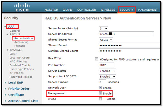
  1. Login to WLC GUI, click Security > AAA > RADIUS > Authentication > New. The RADIUS Authentication server page appears. Click on New to add a server and then enter all the detail.
  2. Check the Management radio button in order to allow the RADIUS Server to authenticate users who login to the WLC.

wlc-ise1


Note: Make sure that the shared secret configured on this WLC will also be the same shared secret on the RADIUS server. Only then the WLC can communicate with the RADIUS server.

  1. Verify whether the WLC is configured to be managed by Cisco ISE. In order to do this, click Security > AAA > RADIUS>Authentication from the WLC GUI.

wlc-ise2


  1. We can see that the Management check box is enabled for RADIUS server 172.99.xx.1. This illustrates that ISE is allowed to authenticate the management users on the WLC.

Step2: Cisco ISE configuration

1)      Add the WLC as an AAA client to the RADIUS server.
2)      Create User Identity Groups for users.
3)      Configure a user with read-write access and assign to specific User Identity Group.
4)      Configure a user with read-only access and assign to specific User Identity Group.
5)      Create Authorization profile and assign Diff. RADIUS IETF attributes for these users.
6)      Create Authentication / Authorization policy for these internal users.


Add the WLC as an AAA Client to the RADIUS Server

Login to ISE the click on Administration > Network Devices > Add then enter the details of WLC and don’t forget to enter same shared secret as we did in WLC.

wlc-ise3

And clicks save.

Create User Identity Groups for users.

To create user identity groups, click on Administration > Identity Management > Groups > User identity Groups > Add then enter the Name and description.

wlc-ise4

Configure a user with read-write access and assign to specific User Identity Group.

RW: username-sandeeprw, password: Testwlc1rw

Click on Administration > Identity Management > Identities > User > Add then enter the details and assign this user to WLC-AdminRW group, save it.

wlc-ise5

Configure a user with read-only access and assign to specific User Identity Group.

RO: username- sandeepro, password: Testwlc123ro

Click on Administration > Identity Management > Identities > User > Add then enter the details and assign this user to WLC-AdminRO group, save it.

wlc-ise6

wlc-ise7

Create Authorization Profile and assign diff. Radius attributes for these users.

To authenticate a user via RADIUS server, for controller login and management, we must add the user to the RADIUS database with the IETF RADIUS attribute Service-Type set to the appropriate value according to the user’s privileges.

  • In order to set read-write privileges for the user, set the Service-Type Attribute to Administrative.
  • In order to set read-only privileges for the user, set the Service-Type Attribute to NAS-Prompt.

Login to ISE GUI then go to Policy > Policy Elements > Results

wlc-ise8

wlc-ise9

Create Authentication / Authorization policy for these internal users

To create Authentication policy: Login to ISE, click on Policy > Authentication.

wlc-ise10

Here is the full policy name:

AuthWLCAdmin: If {DEVICE:Device Type equals All Device Types#Wireless LAN Controller}
 {Allows Protocol: Default Network Access}
 Default: use Internal user

Authorization Policy:

wlc-ise11

Save to apply changes.

Step3: Verification

Now it’s time for testing
First with username: sandeeprw (read write access)

wlc-ise12

username: sandeepro (read only access)

wlc-ise13

Then I tried to create a WLAN with read-only access, the output was “Authorization Failed No sufficient privileges

wlc-ise14

Hence Proved 🙂

WLC WebAuth configuration

In this post we will see how to implement and configure WLC to support internal Webauth.
Web authentication is a Layer 3 security feature that causes the controller to not allow IP traffic (except DHCP and DNS -related packets) from a particular client until that client has correctly supplied a valid username and password.
Web authentication is mostly used to deploy a guest-access network. We must remember that web authentication does not provide data encryption. Webauth is an authentication method without encryption.

Web authentication can be performed using:

  • Default login window on the WLC
  • Modification of the default login window on the WLC
  • A customized login window that we download to the controller
  • A customized login window that we configure on an external web server (External web authentication)

In this post we will only see the starting 3 ways because I don’t have any external webserver.

Let’s start with Configuration of WLC. We will follow these steps:

  1. Create a dynamic interface and fill all the required details.
  2. Create a WLAN and apply the settings.
  3. Configure WLC for Webauth (Internal).
  4. Create local user for testing.
  5. Verification

1. Create a dynamic interface and fill all the required details.

From WLC GUI, Choose Controller > Interface > New and fill the details:
IP Address—10.99.81.1
Netmask—255.255.255.0 (24 bits)
Gateway—10.99.81.254
Port Number—1
Primary DHCP Server—172.99.80.1(WLC Management IP for internal DHCP server)

webauth1

webauth2

Click Apply to save the changes.

2. Create a WLAN and apply the settings:

From the WLC GUI, click WLAN in the menu at the top, and click New on the upper right side. This page will appear. Fill Profile name and SSID.

webauth3

Click Apply.

A new WLANs > Edit window appears.
Check the status box to enable the WLAN.
From the Interface menu, select the name of the VLAN interface (webauth) that we created above.
Check the Broadcast SSID box.

webauth4

Click on Security Tab
Click Layer 2 security and set to None.

webauth5

Click the Layer 3 tab
Check the Web Policy box and choose the Authentication option.

webauth6

Then click Apply from upper right side to save changes.

3. Configure WLC for Webauth(Internal).

Internal web authentication is the by default web authentication type on WLCs. NO need to change the configuration.

4. Create local user for testing:

We can use 3 ways:
Local authentication, RADIUS server, LDAP server
In this post we will tests with Local authentication.

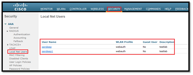
WLC GUI, choose Security > AAA > Local Net Users > New
Enter the username, password and WLAN profile from drop down box.

webauth7

Click Apply
Here we created 2 users:
Username: Sandeep, Password: webauth123
Username: Sandeep1, Password: webauth12345

webauth8
5. Verification

Default login window on the WLC
1. Connect with Webauth WLAN.

webauth9

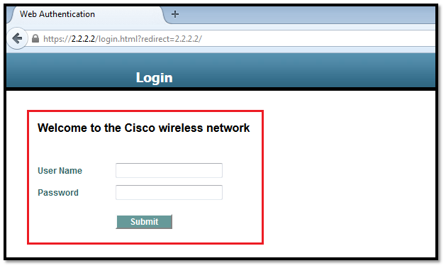
2. Then a new browser will automatically open or we have to manually enter virtual interface IP from WLC : https://1.1.1.1/login.html. A Login window will appears
***In my WLC I have Virtual interface IP as 2.2.2.2

webauth10
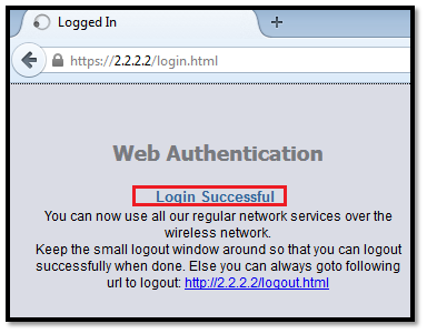
3. Enter the username and password of the Local Net User that we created:
Username: sandeep, Password: webauth123

webauth11
Modification of the default login window on the WLC

1. Login to WLC and modify the default login window by choosing Security > Web Auth > Web Login Page and click on Apply to save it. I changed the headline and message content.

webauth12

2. Now connect to webauth WLAN. Login page will appear like this.
webauth13
3. Enter the username and password.

webauth14

A customized login window that we download to the controller

1. To download a customized login page, first start a TFTP/FTP server and put the login page in their root directory then login to WLC GUI, click on Commands and the details.

webauth15
2. Change the WLAN setting.
WLAN > click on WLAN ID then Security > Layer3,
Select the Over-ride Global Config box
Choose Customized (Downloaded) webauth type from drop down box and select the login and login failure page then click apply.

webauth16
3. Connect to WLAN “webauth” then this login page will appear.

webauth17

4. Enter the username/Password and click on I agree with Policy Above.

webauth18

Here is the complete Web Authentication Process(How it works: )

• We open a web browser and enter a URL, http://www.google.com. The client sends out a DNS request for this URL to get the IP for the destination. The WLC bypasses the DNS request to the DNS server and the DNS server responds back with a DNS reply, which contains the IP address of the destination http://www.google.com. This, in turn, is forwarded to the wireless clients.
*** In my above post I used DNS server as 8.8.8.8

• The client then tries to open a TCP connection with the destination IP address. It sends out a TCP SYN packet destined to the IP address of http://www.google.com.

• The WLC has rules configured for the client and hence can act as a proxy for http://www.google.com. It sends back a TCP SYN-ACK packet to the client with source as the IP address of www. google.com. The client sends back a TCP ACK packet in order to complete the three way TCP handshake and the TCP connection is fully established.

• The client sends an HTTP GET packet destined to www. google.com. The WLC intercepts this packet and sends it for redirection handling. The HTTP application gateway prepares a HTML body and sends it back as the reply to the HTTP GET requested by the client. This HTML makes the client go to the default webpage URL of the WLC, for example, http://<Virtual-Server-IP>/login.html.

• The client closes the TCP connection with the IP address, for example, www. google.com.

• Now the client wants to go to http://2.2.2.2/login.html. Therefore, the client tries to open a TCP connection with the virtual IP address of the WLC. It sends a TCP SYN packet for 2.2.2.2 to the WLC.

• The WLC responds back with a TCP SYN-ACK and the client sends back a TCP ACK to the WLC in order to complete the handshake.

• The client sends a HTTP GET for /login.html destined to 2.2.2.2 in order to request for the login page.

• This request is allowed up to the Web Server of the WLC, and the server responds back with the default login page. The client receives the login page on the browser window where the user can go ahead and log in.

What to study for CCIEW lab

As per Cisco syllabus for CCIEW LAB, Software used are:

We can find all these docs here:

Login to Cisco.com  then click on Support >Products->Wireless

Additional to these:

1. I will try to get latest CCIEW Workbooks or VoD/AoD course from a vendor.

2. Download or read all Cisco tech-note related to specific equipment from Cisco website.

3. Will try to Liston all Videos from Cisco Live.

4. There are many guys who went through the same phase and most of them have there own blog to encourage us:

Here are few (taken from Rasika Blog):

1. http://blakekrone.com/2010/09/23/ccie-wireless-lab-what-did-i-learn
2. http://blakekrone.com/2011/10/26/im-now-known-as-a-number
3. http://cciew.wordpress.com/2011/01/14/wanna-have-some-tips-cco-is-your-friend/
4. http://www.youtube.com/watch?v=E9zgYPz52N4
5. http://revolutionwifi.blogspot.com.au/2011/04/preparing-for-cisco-ccie-lab-exam.html


is it possible to crack CCIEW LAB in first attempt ?(will try…..)

Today with few hesitation Finally booked my slot for LAB exam in Brussels, Belgium. After passing Written exam I was very lazy,went for holidays due to that diverted my attention and then while playing cricket broke my ring finger, its got operated on 13th may and fixed with the help of rod and covered(plaster cast). Nevertheless, I have to start my journey and have to learn many things.

Will crack or not but want to learn as much as possible to motivate my self to get enough knowledge that’s My AIM.

LAB Exam Date: 30 January 2015

CCIEW LAB

I got IPexpert WB volume 1 & 2 and  have small setup in my test LAB that inculdes:

2 X 2504 WLC
2 X 3750 Series Switch
1 X 1242 AG AP
1 X 2602 AP
1 X ISE
1 X PI

I dont have many things but first will read/ learn all Cisco tech-notes,then end of this year will try to practice on Fast-lane/ IP-Expert racks.May be my company will also provide me 5 day instructor training this year(Hope for the best).

I am not thinking about 2nd attempt so please anyone who is going for same path or have already gone through this then please advice/suggest, it will be fruitful for me and as well as for other aspirants.

Only 7 Month left………..


N+1 High Availability Configuration on Cisco 2504WLC

Yesterday I implemented N+1 HA configuration on my lab with Cisco 2504 WLC. Earlier tried to find a guide especially for 2504 Controller but didn’t get on Cisco web. That’s the reason I thought to create a post about this, may be it will be helpful for others.

Few Remembering points:

  • The N+1 HA setup provides redundancy for controllers across separate data centers with low cost of deployment.
  • These WLCs are independent of each other and do not share configuration or IP addresses on any of their interfaces. Each WLC needs to be managed separately, can run a different hardware and a different software version, and can be deployed in different datacenters across the WAN link.
  • We must configure and manage both WLC separately.
  • When a primary WLC resumes operation, the APs fall back from the backup WLC to the primary WLC automatically if the AP fallback option is enabled.

For more info: N+1 HA Deployment Guide

N+1 HA Configuration via GUI:

Step1: Configure both WLC’s and just make sure the hostname and IP address used for management and the dynamic interfaces are different.

Step2: Go to Primary Controller GUI and navigate to Wireless > Access Points > Global Configuration, then configure the backup controller on the primary to point to the secondary controller.

GlobCon

Step3: Configure High Availability to input Primary and Backup controller IP Address at Wireless AP.

Go to Wireless > Access Point > All APs, select specific AP and then Click on High Availability tab.

Enter the primary WLC, secondary WLC IP and name here. Make sure that the WLC name we entered on the AP high availability tab is correct and is case sensitive.

Step4: Configure Mobility Group on both Primary and Secondary Controllers.

Go to Primary WLC GUI then navigate to Controller > Mobility Management > Mobility Groups and then click on new, enter the details of secondary controller.

Mob1

Same on secondary WLC:

Go to Secondary WLC GUI then navigate to Controller > Mobility Management > Mobility Groups and then click on new, enter the details of Primary controller.

Mob2

Step5: Enable Secondary Unit

Via GUI:

Go to Secondary Controller GUI and navigate to Controller then enable the AP Fallback (Enable on both WLC) & HA SKU secondary unit from drop down option.

Via CLI:

Execute the config redundancy unit secondary command to obtain support for Max AP count licenses on a given hardware.

(WLC2) >config redundancy unit ?
 primary        Redundancy unit type is primary
 secondary      Redundancy unit type is secondary
 (WLC2) >config redundancy unit secondary

Make sure:

  1. After this entire configuration we must save the config by Save configuration via GUI or save config from CLI on Both WLCs .
  2. Reboot Secondary WLC to take effect of (config redundancy unit secondary) this command.(According to my test, if you will not reboot this WLC after applying this command AP failover will not happen)

VERIFICATION

(WLC1) >show redundancy summary
 Type of the Unit = Primary
 (WLC1) >
(WLC2) >show redundancy  summary
 Type of the Unit = Secondary
 (WLC2) >

Fast SSID Change

Today I faced an issue on my iPhone while changing SSID, Here is the problem explanation and solution:

Scenario:

WLC have software version 7.0.240.0
WLC Model: AIR-WLC2106-K9

There are two SSID’s from same WLC / AP. If I connected to one and try to connect to other, iPhone shows unable to connect: see the screenshot:

Pic1: Handy connected with RSCCIEW SSID

1

Pic2: When I tried to change to different SSID its show this:

2

Debugs in WLC shows that it’s connected and getting an IP.

(WLC1) >*apfMsConnTask_0: Jun 05 13:56:04.571: 54:26:96:3e:4b:ee Association received from mobile on AP 00:22:bd:98:3a:30
 *apfMsConnTask_0: Jun 05 13:56:04.572: 54:26:96:3e:4b:ee Deleting client immediately since WLAN has changed
 *apfMsConnTask_0: Jun 05 13:56:04.572: 54:26:96:3e:4b:ee Scheduling deletion of Mobile Station:  (callerId: 50) in 1 seconds
 *apfMsConnTask_0: Jun 05 13:56:04.883: 54:26:96:3e:4b:ee Ignoring 802.11 assoc request from mobile pending deletion

But still it’s showing connected and getting IP.

Solution:

There is an option in WLC to enable FAST SSID change. By default its disable.

When fast SSID changing is enabled, the controller allows clients to move between SSIDs. When the client sends a new association for a different SSID, the client entry in the controller connection table is cleared before the client is added to the new SSID. When fast SSID changing is disabled, the controller enforces a delay before clients are allowed to move to a new SSID.

Enable FAST SSID via GUI:

  1. Login WLC GUI: Go to Controller to open the General page.
  2. From the Fast SSID Change drop-down list, choose Enabled to enable this feature
  3. Click Apply
  4. Click Save Configuration on the right side on top.

 4

Enable FAST SSID via CLI:

  1. Enable or disable fast SSID changing by entering this command:

config network fast-ssid-change {enable | disable}

(WLC1) >config network fast-ssid-change ?
 enable/disable] Enable or disables fast SSID changing for mobile stations
(WLC1) >config network fast-ssid-change enable
  1. Save your changes by entering this command:

save config

 (WLC1) >save config
 Are you sure you want to save? (y/n) y
 Configuration Saved!

Pic3: Just after change to enable I tried again and this was the resultJ

3

Thats all we need to switch quickly 🙂