Calling & Called station ID

In this post we will learn / see how there format looks like with an example. It’s very important to know these because in exam we may need to create a policy using this.

My topology:

Client~~~~~~~~~~~AP—————–Switch——————–WLC

Call1

AP Details:

Call2

Default Format:

Called-Station-ID: Normally Contains (1) the MAC address of the Access Point and (2) the SSID on which the wireless device is connecting. These 2 fields are separated by a colon.  Example: “AA-BB-CC-DD-EE-FF:SSID_NAME”.

Calling-Station-ID: Contains the MAC address of the wireless device.  Example: “AA-BB-CC-DD-EE-FF”.

Local mode AP:

Let’s see the log:

***I removed the middle part

Call3

Here our Called-Station ID is: 38-1c-1a-c5-66-20:RSCCIEW

And

Calling Station-ID: F8:16:54:20:F4:C2 (this is from ISE), Normally ACS 5.2 shows like this (F8-16-54-20-F4-C2)

HREAP Connected Mode

*** In HREAP Connected mode it’s the same as in Local mode.

Called-Station ID is: 38-1c-1a-c5-66-20:RSCCIEW

Calling Station-ID: F8-16-54-20-F4-C2

HREAP Standalone Mode

***In HREAP standalone mode its bit different:

Called-Station-ID: 381c.1ac5.6621

*** Its BSSID(We can also find it via command line: show ap wlan 802.11a/b <AP name>)

Calling Station-ID: F816.5420.F4C2

(Not mentioned SSID name in called station-id and also the last number is 21 because its add the WLAN id to its mac address)

*** My wlan id is 2.

ACS Policies based on SSID

If we need to Create Policy in ACL which needs to be include SSID then either we must use the End Station Filters or we need to create a custom profile(Policy Elements > Session Conditions > Custom)

End Station filter:

Policy > Network Conditions > End Station Filters

Create a new and enter the *SSID_Name(example – *RSCCIEW) unders CLI/DNIS.

Call4

Note: *RSCCIEW must be under DNIS but here in ACS it shows under CLI (This is due to bug-CSCtk16271).To resolve this we must click submit again to swap these entry.

Custom Profile:

Then click on Create, give the name to this custom profile.

Under Condition Tab:

We must use Dictionary: Radius-IETF

Attribute: Called-Station-ID

Policy Elements > Session Conditions > Custom

Call5

That’s all about Calling and Called Station ID 🙂 don’t have much time otherwise would love to go more in to details.

WGB Roaming

In this post we will try to understand how WGB scan the parent channels or try to roam from one parent to other. It is really important to implement roaming commands on WGB to keep the session alive.

Basic Info:

  • WGB is mobile device
  • Normally Companies uses WGB in Production and it’s mounted on forklift or on a cart with their device. Roaming is very critical part of it and it must be smooth otherwise it disconnects frequently and try to reconnect to other AP.
  • As roaming needs a change from the current AP to the next, there is a resultant disconnection or time without service. This disconnection can be small.
  • Roaming is needed WGB find an AP which has better signal then the current one, and it can continue to access the network infrastructure properly.
  • Too many roams can cause disconnections (it’s not acceptable in especially in production or may be in hospital), which affects access.
  • It is really important for a WGB, to have a good roaming algorithm with enough configuration capabilities to adapt to different RF environments and data needs.

Configure Roaming:

***By default it acts a normal client and it scans another parent after continuous 8 beacon loss.

But in case of WGB we have few other methods on top of this default setting.

Let’s see these in details:

Mobile station:

This commands mark the unit as Mobile to speed up roaming

WGB# conf t
WGB(config-if)#mobile station

When we enable this WGB scans for a new parent when the RSSI to its AP gets too poor or when it has too many retransmits. This makes that the WGB will roam. When the mobile station setting is disabled (the default setting) the workgroup bridge does not search for a new AP until it loses its current association.

Scanning Channels:

WGB(config-if)#mobile station scan 1 6 11

mobile station scan <set of channels> command  is used to invoke scanning to specified channels.

By default there is no limitation of channels that can be configured. When we run this command, the WGB only scans these channels.

In our case, we configured our WGB to only scan these channels, instead of scanning all channels.

***Mobile station only shows up when using the WGB role on the radio.

*** Make sure our WGB scan list matches our infrastructure channel list. If not, the WGB will not find our available APs.

RSSI Monitoring:

WGB(config-if)#mobile station period 4 threshold 70

WGB can have a pro-active signal scan for the current parent and start a new roaming process when the signal falls below an expected level.

This has two parameters:

  • A timer, which wakes up the check process every X seconds
  • RSSI level, which is used to start a roaming process if the current signal is bellow it.

Minimum Data Rate:

WGB(config-if)#mobile station minimum-rate 18.0

This command states that WGB must trigger a new roaming event, if the current data rate to parent is bellow a given value.

*** This is too aggressive, and normally, the only solution was to configure a single data rate both in WGB and on parent APs.

By using this command, the new roaming process is only starts when the current rate is lower than the 18Mb/s. This reduces unnecessary roaming.

CCX Neighbors:

WGB(config-if)#mobile station ignore neighbor-list

Normally when WGB scan the channels, it prepares the list of available APs. This is a CCX mechanism by which the WGB can transmit to its AP the details of the others APs the WGB heard. But if we configured WGB for only specific channels scanning then it does not need to process the CCX reports to update its known channel list.

*** We use the mobile station ignore neighbor-list command to disable processing of CCX neighbor list reports

Packet retries:

WGB(config-if)#packet retries 128

By default, the WGB re-transmits a frame 64 times. (1- 128 range can be configured)

If it is not acknowledged by a parent AP then it starts roaming process.

Drop-Packet:

If after 128 tries WGB don’t find any ACK from parent AP then WGB starts a roaming. But when parent is present, the WGB does not start new roaming and uses other triggers, such as beacon loss and signal.

So the complete command is:

WGB(config-if)#packet retries 128 drop-packet

*** This command must be configured on both side(on WGB as well as on Parent AP under radio interface).

WGB(config-if)#mobile ?
 station  Mark the unit as mobile to speed up roaming
WGB(config-if)#mobile station ?
 ignore        ignore CCX reports
 minimum-rate  Minimum rate below which the AP is rejected
 period        Minimum time between scans when the connection deteriorates
 scan          Scan the following channels only
 <cr>
WGB(config)#int d0
WGB(config-if)#packet retries 128 drop-packet
RootAP#debug dot11 dot11radio 0 trace print uplink
RootAP#debug dot11 dot11radio 0 trace print rates
WGB(config-if)#
 *Mar  1 19:27:56.501: %LINK-5-CHANGED: Interface Dot11Radio0, changed state to reset
 *Mar  1 19:27:56.502: FAD9916A-0 Uplink: Stop
 *Mar  1 19:27:56.502: FAD991BA-0 Interface down
 *Mar  1 19:27:56.521: %LINK-3-UPDOWN: Interface Dot11Radio0, changed state to up
 *Mar  1 19:27:56.522: FAD9E7DA-0 Interface up
 *Mar  1 19:27:56.523: FAD9E82B-0 Uplink: Wait for driver to stop
 *Mar  1 19:27:56.523: FAD9E8A4-0 Uplink: Enabling active scan
 *Mar  1 19:27:56.523: FAD9E8B7-0 Uplink: Not busy, scan all channels
 *Mar  1 19:27:56.523: FAD9E8C7-0 Uplink: Scanning
 *Mar  1 19:27:56.584: FADAE016-0 Uplink: Rcvd response from 003a.9a3e.a380 channel 11 10283
 *Mar  1 19:27:56.589: FADAF3F1-0 Uplink: dot11_uplink_scan_done: rsnie_accept returns 0x0 key_mgmt 0xFAC01 encrypt_type 0x200
 *Mar  1 19:27:56.589: FADAF42C-0 Uplink: ssid RSCCIEW auth leap
 *Mar  1 19:27:56.589: FADAF43F-0 Uplink: try 003a.9a3e.a380, enc 200 key 3, priv 1, eap 11
 *Mar  1 19:27:56.590: FADAF45E-0 Uplink: Authenticating
 *Mar  1 19:27:56.599: FADB19F9-0 Uplink: Associating
 *Mar  1 19:27:56.608: FADB2EBC-0 3EA380 - Set rate:    54.0  54 Mbps ( 6C), Rssi 24 dBm
 *Mar  1 19:27:56.609: FADB3018-0 Uplink: EAP authenticating
 *Mar  1 19:27:56.668: %DOT11-4-UPLINK_ESTABLISHED: Interface Dot11Radio0, Associated To AP RootAP 003a.9a3e.a380 [LEAP WPAv2]
 *Mar  1 19:27:56.670: FADC277E-0 Uplink: Done

These are the other timers on WGB:

WGB(config)#workgroup-bridge timeouts ?
 assoc-response  Association Response time-out value
 auth-response   Authentication Response time-out value
 client-add      client-add time-out value
 eap-timeout     EAP Timeout value
 iapp-refresh    IAPP Refresh time-out value

Autonomous AP as WGB (Multiple VLAN)

In this post we will learn how to configure an autonomous AP as WGB with Multiple VLAN.

How to setup Root AP and WGB: Check this post

***I don’t have extra switch so I will force WGB to connect to clicnet in vlan 12.

***In my post WGB and Root AP both are on vlan 11(Native) and Client will get the IP in vlan 12.

*** Link between RootAP and switch is trunk.

Switch Config:

 Int fa0/24
 Switchport trunk encapsulation dot1q
 Switchport trunk native vlan 11
 Switchport trunk allowed vlan 11,12
 Switchport mode trunk

 WGB_2vlan

Remembering Points:

  1. The AP to which a WGB associates can treat the WGB as an infrastructure device or as a normal client. By default, AP treats WGB as client devices.
  1. If WGB is an infrastructure client, it can associate to an infrastructure SSID. Infrastructure SSIDs are used to authenticate Bridges, Repeaters…Etc. A WGB in by default is a “client”, not an “infrastructure client” and therefore cannot associate to an infrastructure SSID.

Use of Infrastructure-Client Command:

  1. Used for Reliable Multicast
  2. To make WGB as Infrastructure-Client so that WGB can associate to Infrastructure-SSID.

In my example WGB is connected root AP via RSCCIEW WLAN interface.

WGB authentication with LEAP-WPA2.

Here is the complete configuration:

Root AP:

RootAP#sh run
 !
 hostname RootAP
 !
 aaa new-model
 !
 aaa group server radius rad_eap
 server 192.168.11.35 auth-port 1112 acct-port 1113
 !
 aaa authentication login eap_method group rad_eap
 !
 dot11 ssid RSCCIEW
 vlan 11
 authentication open eap eap_method
 authentication network-eap eap_method
 authentication key-management wpa version 2
 infrastructure-ssid
 !
 interface Dot11Radio0
 no ip address
 no ip route-cache
 !
 encryption vlan 11 mode ciphers aes-ccm
 !
 ssid RSCCIEW
 !
 station-role root
 infrastructure-client
 !
 interface Dot11Radio0.11
 encapsulation dot1Q 11 native
 no ip route-cache
 bridge-group 1
 bridge-group 1 subscriber-loop-control
 bridge-group 1 block-unknown-source
 no bridge-group 1 source-learning
 no bridge-group 1 unicast-flooding
 bridge-group 1 spanning-disabled
 !
 interface Dot11Radio0.12
 encapsulation dot1Q 12
 no ip route-cache
 bridge-group 12
 bridge-group 12 subscriber-loop-control
 bridge-group 12 block-unknown-source
 no bridge-group 12 source-learning
 no bridge-group 12 unicast-flooding
 bridge-group 12 spanning-disabled
 !
 interface Dot11Radio1
 no ip address
 no ip route-cache
 shutdown
 no dfs band block
 channel dfs
 station-role root
 bridge-group 1
 bridge-group 1 subscriber-loop-control
 bridge-group 1 block-unknown-source
 no bridge-group 1 source-learning
 no bridge-group 1 unicast-flooding
 bridge-group 1 spanning-disabled
 !
 interface FastEthernet0
 ip address dhcp
 no ip route-cache
 speed 100
 full-duplex
 !
 interface FastEthernet0.11
 encapsulation dot1Q 11 native
 no ip route-cache
 bridge-group 1
 no bridge-group 1 source-learning
 bridge-group 1 spanning-disabled
 !
 interface FastEthernet0.12
 encapsulation dot1Q 12
 no ip route-cache
 bridge-group 12
 no bridge-group 12 source-learning
 bridge-group 12 spanning-disabled
 !
 interface BVI1
 ip address 192.168.11.35 255.255.255.0
 no ip route-cache
 !
 ip default-gateway 192.168.11.254
 radius-server local
 no authentication eapfast
 no authentication mac
 nas 192.168.11.35 key 7 13261E010803557878
 user WGB nthash 7 124C264F425B2A55790A770B166D743623445655067D7C077159504B477C017601
 !
 radius-server host 192.168.11.35 auth-port 1112 acct-port 1113 key 7 02250D4808095E731F
 bridge 1 route ip
 !
 end

WGB:

WGB#sh run
 !
 hostname WGB
 !
 no aaa new-model
 !
 dot11 ssid RSCCIEW
 vlan 11
 authentication open eap test
 authentication network-eap test
 authentication key-management wpa version 2
 dot1x credentials wgbuser
 dot1x eap profile leap
 infrastructure-ssid
 !
 eap profile leap
 method leap
 !
 dot1x credentials wgbuser
 username WGB
 password 7 060506324F41
 !
 interface Dot11Radio0
 no ip address
 no ip route-cache
 !
 encryption vlan 11 mode ciphers aes-ccm
 !
 ssid RSCCIEW
 !
 station-role workgroup-bridge
 !
 interface Dot11Radio0.11
 encapsulation dot1Q 11 native
 no ip route-cache
 bridge-group 1
 !
 interface Dot11Radio0.12
 encapsulation dot1Q 12
 no ip route-cache
 bridge-group 12
 !
 interface Dot11Radio1
 no ip address
 no ip route-cache
 shutdown
 no dfs band block
 channel dfs
 station-role root
 bridge-group 1
 bridge-group 1 subscriber-loop-control
 bridge-group 1 block-unknown-source
 no bridge-group 1 source-learning
 no bridge-group 1 unicast-flooding
 bridge-group 1 spanning-disabled
 !
 interface FastEthernet0
 no ip address
 no ip route-cache
 duplex auto
 speed auto
 !
 interface FastEthernet0.11
 encapsulation dot1Q 11 native
 no ip route-cache
 bridge-group 1
 !
 interface FastEthernet0.12
 encapsulation dot1Q 12
 no ip route-cache
 bridge-group 12
 !
 interface BVI1
 ip address dhcp
 no ip route-cache
 !
 bridge 1 route ip
 bridge 1 address c434.6b27.0c11 forward FastEthernet0.12 --> To make permanent Entry in WGB bridge TABLE
 !
 workgroup-bridge client-vlan 12
 end

Verification:

On Root AP:

 RootAP#sh dot11 ass
 802.11 Client Stations on Dot11Radio0:
 SSID [RSCCIEW] :
 MAC Address    IP address      Device        Name            Parent         State
 001d.7096.3404 192.168.11.36     WGB           WGB             self           EAP-Assoc
 c434.6b27.0c11 192.168.12.31     WGB-client    -               001d.7096.3404 Assoc
RootAP#sh dot11 ass 001d.7096.3404
 Address           : 001d.7096.3404     Name             : WGB
 IP Address        : 192.168.11.36        Interface        : Dot11Radio 0
 Device            : WGB                Software Version : 12.4
 CCX Version       : 5                  Client MFP       : On
 State             : EAP-Assoc          Parent           : self
 SSID              : RSCCIEW
 VLAN              : 11
 Hops to Infra     : 1                  Association Id   : 1
 Clients Associated: 1                  Repeaters associated: 0
 Tunnel Address    : 0.0.0.0
 Key Mgmt type     : WPAv2              Encryption       : AES-CCMP
 Current Rate      : 54.0               Capability       : WMM ShortHdr ShortSlot
 Supported Rates   : 1.0 2.0 5.5 11.0 6.0 9.0 12.0 18.0 24.0 36.0 48.0 54.0
 Voice Rates       : disabled           Bandwidth        : 20 MHz
 Signal Strength   : -22  dBm           Connected for    : 55931 seconds
 Signal to Noise   : 73  dB            Activity Timeout : 30 seconds
 Power-save        : Off                Last Activity    : 1 seconds ago
 Apsd DE AC(s)     : NONE
 Packets Input     : 9399               Packets Output   : 30671
 Bytes Input       : 1597644            Bytes Output     : 4718946
 Duplicates Rcvd   : 0                  Data Retries     : 1325
 Decrypt Failed    : 2                  RTS Retries      : 0
 MIC Failed        : 0                  MIC Missing      : 0
 Packets Redirected: 0                  Redirect Filtered: 0
 Session timeout   : 0 seconds
 Reauthenticate in : never
RootAP#sh dot11 ass c434.6b27.0c11
 Address           : c434.6b27.0c11     Name             : NONE
 IP Address        : 192.168.12.31        Interface        : Dot11Radio 0
 Device            : WGB-client         Software Version : NONE
 CCX Version       : NONE               Client MFP       : Off
 State             : Assoc              Parent           : 001d.7096.3404
 SSID              : RSCCIEW
 VLAN              : 12
 Hops to Infra     : 0
 Clients Associated: 0                  Repeaters associated: 0

On WGB:

WGB#sh dot11 ass
 802.11 Client Stations on Dot11Radio0:
 SSID [RSCCIEW] :
 MAC Address    IP address      Device        Name            Parent         State
 003a.9a3e.a380 192.168.11.35     ap1240-Parent RootAP          -              EAP-Assoc
WGB#sh dot11 ass 003a.9a3e.a380
 Address           : 003a.9a3e.a380     Name             : RootAP
 IP Address        : 192.168.11.35        Interface        : Dot11Radio 0
 Device            : ap1240-Parent      Software Version : 12.4
 CCX Version       : 5                  Client MFP       : On
 State             : EAP-Assoc          Parent           : -
 SSID              : RSCCIEW
 VLAN              : 11
 Hops to Infra     : 0                  Association Id   : 1
 Tunnel Address    : 0.0.0.0
 Key Mgmt type     : WPAv2              Encryption       : AES-CCMP
 Current Rate      : 54.0               Capability       : WMM ShortHdr ShortSlot
 Supported Rates   : 1.0 2.0 5.5 11.0 6.0 9.0 12.0 18.0 24.0 36.0 48.0 54.0
 Voice Rates       : disabled           Bandwidth        : 20 MHz
 Signal Strength   : -24  dBm           Connected for    : 55975 seconds
 Signal to Noise   : 69  dB            Activity Timeout : 14 seconds
 Power-save        : Off                Last Activity    : 1 seconds ago
 Apsd DE AC(s)     : NONE
 Packets Input     : 586784             Packets Output   : 9346
 Bytes Input       : 102345033          Bytes Output     : 1669240
 Duplicates Rcvd   : 0                  Data Retries     : 12
 Decrypt Failed    : 114                RTS Retries      : 0
 MIC Failed        : 0                  MIC Missing      : 0
 Packets Redirected: 0                  Redirect Filtered: 0

Normally its not recommended by cisco to use multiple vlan on WGB 🙂

Autonomous AP as WGB (Single VLAN)

In this post we will learn how to configure an autonomous AP as WGB.

WGB can provide the wired connection to the devices which don’t have wireless adaptor so that device can directly connect to WGB Ethernet port to access the wireless network.

It can provide wireless connectivity to wired clients that are connected by Ethernet to the work-group bridge access point.00

WGB connect to root AP as a client through the wireless interface.

Basic Info:

  • Infrastructure SSID configuration not required
  • By default when the WGB associates with the root bridge, all the wired clients + the WGB are shown as normal clients.
  • A WGB can only pass one VLAN between the WGB and the root bridge(As Cisco recommend but it can also pass multiple)
  • Always use bridge-group 1 for the link between the root and WGB.
  • But if we use WGB multicast infrastructure mode on the WGB, we need to add infrastructure-client on the root AP side.
  • A WGB in standard mode is by default a “client”, not an “infrastructure client” and therefore cannot associate to an infrastructure SSID.
  • WGB is a mobile
  • Root AP can allow max 20WGB.(This must be test out)

 My Topology:

WGB_Vlan1

Remembering Points:

  1. The AP to which a WGB associates can treat the WGB as an infrastructure device or as a normal client. By default, AP treats WGB as client devices.
  1. If WGB is an infrastructure client, it can associate to an infrastructure SSID. Infrastructure SSIDs are used to authenticate Bridges, Repeaters…Etc. A WGB in by default is a “client”, not an “infrastructure client” and therefore cannot associate to an infrastructure SSID.

Use of Infrastructure-Client Command:

  1. Used for Reliable Multicast
  2. To make WGB as Infrastructure-Client so that WGB can associate to Infrastructure-SSID.

In my example WGB is connected root AP via RSCCIEW WLAN interface.

WGB authentication with LEAP-WPA2.

Here is the configuration:

Root AP:

RootAP#sh run
 !
 hostname RootAP
 !
 aaa new-model
 !
 aaa group server radius rad_eap
 server 192.168.11.35 auth-port 1112 acct-port 1113
 !
 aaa authentication login eap_method group rad_eap
 !
 dot11 ssid RSCCIEW
 vlan 11
 authentication open eap eap_method
 authentication network-eap eap_method
 authentication key-management wpa version 2
 !
 interface Dot11Radio0
 no ip address
 no ip route-cache
 !
 encryption vlan 11 mode ciphers aes-ccm
 !
 ssid RSCCIEW
 !
 station-role root
 !
 interface Dot11Radio0.11
 encapsulation dot1Q 11 native
 no ip route-cache
 bridge-group 1
 bridge-group 1 subscriber-loop-control
 bridge-group 1 block-unknown-source
 no bridge-group 1 source-learning
 no bridge-group 1 unicast-flooding
 bridge-group 1 spanning-disabled
 !
 interface Dot11Radio1
 no ip address
 no ip route-cache
 shutdown
 no dfs band block
 channel dfs
 station-role root
 bridge-group 1
 bridge-group 1 subscriber-loop-control
 bridge-group 1 block-unknown-source
 no bridge-group 1 source-learning
 no bridge-group 1 unicast-flooding
 bridge-group 1 spanning-disabled
 !
 interface FastEthernet0
 ip address dhcp
 no ip route-cache
 speed 100
 full-duplex
 !
 interface FastEthernet0.11
 encapsulation dot1Q 11 native
 no ip route-cache
 bridge-group 1
 no bridge-group 1 source-learning
 bridge-group 1 spanning-disabled
 !
 interface BVI1
 ip address 192.168.11.35 255.255.255.0
 no ip route-cache
 !
 ip default-gateway 192.168.11.254
 radius-server local
 no authentication eapfast
 no authentication mac
 nas 192.168.11.35 key 7 13261E010803557878
 user WGB nthash 7 124C264F425B2A55790A770B166D743623445655067D7C077159504B477C017601
 !
 radius-server host 192.168.11.35 auth-port 1112 acct-port 1113 key 7 02250D4808095E731F
 bridge 1 route ip
 !
 end

WGB:

WGB#sh run
 !
 hostname WGB
 !
 no aaa new-model
 !
 dot11 ssid RSCCIEW
 authentication open eap test
 authentication network-eap test
 authentication key-management wpa version 2
 dot1x credentials wgbuser
 dot1x eap profile leap
 !
 eap profile leap
 method leap
 !
 dot1x credentials wgbuser
 username WGB
 password 7 060506324F41
 !
 interface Dot11Radio0
 no ip address
 no ip route-cache
 !
 encryption mode ciphers aes-ccm
 !
 ssid RSCCIEW
 !
 station-role workgroup-bridge
 bridge-group 1
 !
 interface Dot11Radio1
 no ip address
 no ip route-cache
 shutdown
 no dfs band block
 channel dfs
 station-role root
 bridge-group 1
 bridge-group 1 subscriber-loop-control
 bridge-group 1 block-unknown-source
 no bridge-group 1 source-learning
 no bridge-group 1 unicast-flooding
 bridge-group 1 spanning-disabled
 !
 interface FastEthernet0
 no ip address
 no ip route-cache
 duplex auto
 speed auto
 bridge-group 1
 !
 interface BVI1
 ip address dhcp
 no ip route-cache
 !
 bridge 1 route ip
 bridge 1 address c434.6b27.0c11 forward FastEthernet0.11
 !
 end

Verification:

On Root AP

RootAP#sh dot11 associations
 802.11 Client Stations on Dot11Radio0:
 SSID [RSCCIEW] :
 MAC Address    IP address      Device        Name            Parent         State
 001d.7096.3404 192.168.11.36     WGB           WGB             self           EAP-Assoc
 c434.6b27.0c11 192.168.11.37     WGB-client    -               001d.7096.3404 Assoc
RootAP#sh dot11 associations 001d.7096.3404
 Address           : 001d.7096.3404     Name             : WGB
 IP Address        : 192.168.11.36        Interface        : Dot11Radio 0
 Device            : WGB                Software Version : 12.4
 CCX Version       : 5                  Client MFP       : On
 State             : EAP-Assoc          Parent           : self
 SSID              : RSCCIEW
 VLAN              : 11
 Hops to Infra     : 1                  Association Id   : 1
 Clients Associated: 1                  Repeaters associated: 0
 Tunnel Address    : 0.0.0.0
 Key Mgmt type     : WPAv2              Encryption       : AES-CCMP
 Current Rate      : 54.0               Capability       : WMM ShortHdr ShortSlot
 Supported Rates   : 1.0 2.0 5.5 11.0 6.0 9.0 12.0 18.0 24.0 36.0 48.0 54.0
 Voice Rates       : disabled           Bandwidth        : 20 MHz
 Signal Strength   : -24  dBm           Connected for    : 102 seconds
 Signal to Noise   : 71  dB            Activity Timeout : 30 seconds
 Power-save        : Off                Last Activity    : 0 seconds ago
 Apsd DE AC(s)     : NONE
 Packets Input     : 213                Packets Output   : 29
 Bytes Input       : 47472              Bytes Output     : 3382
 Duplicates Rcvd   : 0                  Data Retries     : 3
 Decrypt Failed    : 0                  RTS Retries      : 0
 MIC Failed        : 0                  MIC Missing      : 0
 Packets Redirected: 0                  Redirect Filtered: 0
 Session timeout   : 0 seconds
 Reauthenticate in : never
RootAP#sh dot11 associations c434.6b27.0c11
 Address           : c434.6b27.0c11     Name             : NONE
 IP Address        : 192.168.11.37        Interface        : Dot11Radio 0
 Device            : WGB-client         Software Version : NONE
 CCX Version       : NONE               Client MFP       : Off
 State             : Assoc              Parent           : 001d.7096.3404
 SSID              : RSCCIEW
 VLAN              : 11
 Hops to Infra     : 0
 Clients Associated: 0                  Repeaters associated: 0

On WGB:

 *Mar  1 02:06:37.718: %DOT11-4-UPLINK_ESTABLISHED: Interface Dot11Radio0, Associated To AP RootAP 003a.9a3e.a380 [LEAP WPAv2]
  
  
 WGB#sh dot11 associations
 802.11 Client Stations on Dot11Radio0:
 SSID [RSCCIEW] :
 MAC Address    IP address      Device        Name            Parent         State
 003a.9a3e.a380 192.168.11.35     ap1240-Parent RootAP          -              EAP-Assoc
  
 WGB#sh dot11 associations 003a.9a3e.a380
 Address           : 003a.9a3e.a380     Name             : RootAP
 IP Address        : 192.168.11.35        Interface        : Dot11Radio 0
 Device            : ap1240-Parent      Software Version : 12.4
 CCX Version       : 5                  Client MFP       : On
 State             : EAP-Assoc          Parent           : -
 SSID              : RSCCIEW
 VLAN              : 0
 Hops to Infra     : 0                  Association Id   : 1
 Tunnel Address    : 0.0.0.0
 Key Mgmt type     : WPAv2              Encryption       : AES-CCMP
 Current Rate      : 54.0               Capability       : WMM ShortHdr ShortSlot
 Supported Rates   : 1.0 2.0 5.5 11.0 6.0 9.0 12.0 18.0 24.0 36.0 48.0 54.0
 Voice Rates       : disabled           Bandwidth        : 20 MHz
 Signal Strength   : -28  dBm           Connected for    : 177 seconds
 Signal to Noise   : 66  dB            Activity Timeout : 11 seconds
 Power-save        : Off                Last Activity    : 4 seconds ago
 Apsd DE AC(s)     : NONE
 Packets Input     : 2475               Packets Output   : 732
 Bytes Input       : 402607             Bytes Output     : 316070
 Duplicates Rcvd   : 0                  Data Retries     : 4
 Decrypt Failed    : 0                  RTS Retries      : 0
 MIC Failed        : 0                  MIC Missing      : 0
 Packets Redirected: 0                  Redirect Filtered: 0

Certificate Installation on ACS

First we will start with Root CA Certificate installation:

Login to Certificate server http://<ip or xyz>/certsrv

Click on “Download a CA Certificate, certificate chain or CRL

ACS1

Select the Encoding Method „Base 64“and click on Download CA certificate.

ACS2

ACS3

Save it to a location on our file system.

Now we have Root CA, it’s time to install Root CA on ACS.

Login to ACS, go to Users and Identity Stores > External Identity Stores > Certificate Authorities

Click on Add.

ACS4

Now Browse the Root CA, tick the check box “Trust for client with EAP-TLS” (Specially for EAP-TLS authentication) otherwise we will get error…example: 12514 (Failed SSL/TLS handshake)

Then click on Submit.

ACS5

Now we will Download /Install the ACS local server Certificate:

We must use these steps:

  1. Go to System Administration > Local Certificates, then click on Add
  2. Select Generate Certificate Signing Request:
  3. Fill the Certificate Subject name, Key length. Click Submit.

ACS6

Select third option “Generate Certificate Signing Request

ACS7

Click Next.

Enter the Certificate subject name.

Choose key length to 1024 or 4096 (Max value).

ACS8

Click Finish, this prompt will popup.

ACS9

Click OK. Now we can this signing request under Outstanding signing Request.

ACS10

Now Tick the request and click Export.

ACS11

Save it and open in notepad.

ACS12

Copy it

Login backup to certificate server and this time click on Request a Certificate.

ACS13

ACS14

ACS15

Paste the certificate signing request here (Which we opened in notepad)

**Select Web Server

ACS16

Download the Base 64 coded certificate. Click “Download certificate

ACS17

ACS18

Save it.

Now login again to ACS, select Bind CA signed Certificate

ACS19

Click Next, browse the Certificate here.

Also tick EAP and Management interface and click Submit.

ACS20

ACS21

Select OK and Click Finish.

Sometime we need to reboot ACS to complete the certificate installation.

That’s all About ACS certificate installation 🙂

AP Joining Issue to WLC Running 8.0.100.0

In this post I will discuss about the issue faced today while joing AP to WLC version 8.0.100.0.

5 Day before I got a new 2602 AP and Today I tried to connect to my switch in right AP VLAN. I saw that AP got IP address from DHCP pool and WLC IP via DHCP Option 43 and AP start updating the Image from WLC.

I was relaxed that it is working so I will test my Important topic like Auto Anchor, Static IP tunneling & Foreign mapping.

After 1-2 minutes I saw that there was some kind of failure which I never seen, here are the logs:

TestAP#
 *Nov 19 13:37:59.999: AP has SHA2 MIC certificate - Using SHA2 MIC certificate for DTLS.
 *Nov 19 13:38:00.000: %CAPWAP-5-DTLSREQSEND: DTLS connection request sent peer_ip: 192.168.10.3 peer_port: 5246
 *Nov 19 13:38:29.999: DTLS_CLIENT_ERROR: ../capwap/base_capwap/dtls/base_capwap_dtls_connection_db.c:2214 Max retransmission count reached for Connection 0x8D69EB4!
 *Nov 19 13:38:59.999: %DTLS-5-SEND_ALERT: Send FATAL : Close notify Alert to 192.168.10.3:5246
 *Nov 19 13:38:59.999: AP has SHA2 MIC certificate - Using SHA2 MIC certificate for DTLS.
 *Nov 19 13:39:00.000: %CAPWAP-5-DTLSREQSEND: DTLS connection request sent peer_ip: 192.168.10.1 peer_port: 5246Peer certificate verification failed FFFFFFFF
 *Nov 19 13:39:00.099: DTLS_CLIENT_ERROR: ../capwap/base_capwap/capwap/base_capwap_wtp_dtls.c:496 Certificate verified failed!
 *Nov 19 13:39:00.099: %DTLS-5-SEND_ALERT: Send FATAL : Bad certificate Alert to 192.168.10.1:5246
 *Nov 19 13:39:00.099: %DTLS-5-SEND_ALERT: Send FATAL : Close notify Alert to 192.168.10.1:5246
 TestAP#

After googling I got this: APs mfg in September/October 2014 unable to join an AireOS controller CSCur43050

Description

Symptom:
New Aironet APs with factory installed recovery IOS are able to join the controller 8.0.100.0 and download 15.3(3)JA IOS. But after the AP reload, the APs are unable to join the controller. On the AP, logs similar to the following are seen:

*Oct 16 12:39:06.231: AP has SHA2 MIC certificate - Using SHA2 MIC certificate for DTLS.
 *Oct 16 13:14:56.000: %CAPWAP-5-DTLSREQSEND: DTLS connection request sent peer_ip: ***.***.***.*** peer_port: 5246Peer certificate verification failed FFFFFFFF
 *Oct 16 13:14:56.127: DTLS_CLIENT_ERROR: ../capwap/base_capwap/capwap/base_capwap_wtp_dtls.c:496 Certificate verified failed!
 *Oct 16 13:14:56.127: %DTLS-5-SEND_ALERT: Send FATAL : Bad certificate Alert to ***.***.***.***:5246
 *Oct 16 13:14:56.127: %DTLS-5-SEND_ALERT: Send FATAL : Close notify Alert to ***.***.***.***:5246

Another symptom of this problem is that the AP may be able to join the 8.0.100.0 controller, download the IOS code, boot up and join the controller OK … but when it goes to upgrade to newer 8.x code, it gets stuck in a loop failing the download.

Conditions:
Seen only with APs that were manufactured in September or October, 2014 – all Aironet APs were affected EXCEPT the 700 series. Seen with WLCs running 8.0.100.0 or an 8.0.100.x special.

If the WLC was manufactured in September 2014, or later (i.e. has a SHA2 MIC), then the first symptom is seen, i.e. the AP joins the 8.0.100 WLC, downloads the image, but then fails to rejoin.

If the WLC was manufactured before September 2014 (i.e. does not have a SHA2 MIC), then the second symptom is seen, i.e. the AP can join the 8.0.100 WLC OK, but then will fail download during a subsequent upgrade.

Also seen with new APs trying to join a controller running IOS-XE 3.6.0 (15.3(3)JN k9w8 image.) (Track CSCur50946 for the IOS-XE fix)

Workaround:
Downgrade to AireOS 7.6.130.0, or to IOS-XE 3.3, if the APs are supported in the earlier code.

Further Problem Description:
This problem affects only APs that were manufactured with incorrect SHA2
certificates. APs with only SHA1 certificates are not affected. To determine
whether an AP is affected, use the following AP exec commands (while the AP
has a 15.3(3)/8.0 image installed):

1. Check for the presence of a SHA2 Parameter Block:

ap#test pb display

if the output of this command includes:

SHA2 Parameter Block Doesn’t have any Records

then this AP is not affected. If the output of this command shows

Display of the SHA2 Parameter Block

then

2. See whether a correct SHA2 certificate is present:

ap#show crypto pki trustpoints | include SHA2

if there is no valid SHA2 certificate, then this will show no output.
If there is a valid SHA2 cert, this will show:

cn=Cisco Manufacturing CA SHA2

Only APs which *do* have a SHA2 Parameter Block and which *do not* have
a valid SHA2 certificate are affected by this bug.

The problem symptoms will vary according to whether or not the WLC has a
SHA2 certificate installed. To verify this, use the following command on
the AireOS CLI:

Cisco Controller) >show certificate all
and look for:
Certificate Name: Cisco SHA2 device cert

Then I downgraded my WLC to version 7.6.130.0 and it worked.
So this just a small post, it may help those who is/will get this kinda problem.

Auto-Anchor Mobility / Guest Tunneling

In this post we will learn how to use Auto Anchoring feature.

In simple words, Auto-anchoring is when we anchor a WLAN to a particular controller in the mobility domain or group.

It can be used for load balancing & Security. We can force clients to be on a particular controller regardless of the controller they access the wireless network from.

**The most common example/use for auto-anchor is with guest networking.

Let’s go into detail:

With auto-anchor, regardless of which controller’s APs a client associates with, the client traffic is anchored to this one controller. Auto-anchoring is basically symmetric tunneling using a fixed anchor. When a client first associates with a controller on an anchored WLAN, a Local Session entry is created for the client. The controller sends out a Mobile Announce message to the mobility group.

When that message is not answered, the foreign controller contacts the configured anchor controller and creates a foreign session for the client in its database. The anchor controller then creates an Anchor session for the client.

All traffic to and from the client associated with an anchored WLAN passes through the anchor controller. This is known as a bidirectional tunnel because the foreign controller encapsulates the client packets in EtherOverIP and sends them to the anchor. The anchor de-encapsulates the packets and delivers them to the wired network. Packets destined for the client are encapsulated in the EtherOverIP tunnel by the anchor and sent to the foreign controller. The foreign controller de-encapsulates the packets and forwards them to the client.

Guideline before Auto-Anchor configuration:

  1. We must add controllers to the mobility group member list before we can designate them as mobility anchors for a WLAN. How to Add, Check this post: Mobility Configuration on WLC
  2. We can configure multiple controllers as mobility anchors for a WLAN.
  3. We must disable the WLAN before configuring mobility anchors for it.
  4. Auto-anchor mobility supports web authorization but does not support other Layer 3 security types.
  5. We must configure the WLANs on both the foreign controller and the anchor controller with mobility anchors. On the anchor controller, configure the anchor controller itself as a mobility anchor. On the foreign controller, configure the anchor as a mobility anchor.
  6. Auto-anchor mobility is not supported for use with DHCP option 82.
  7. When using the mobility failover features with a firewall, make sure that the following ports are open:
  • UDP 16666 for tunnel control traffic
  • IP Protocol 97 for user data traffic
  1. To check the connectivity and peer kee-palive timers, use these CLI commands :
  • mping peer-ip-address – used to test the Control Path between mobility peers
  • eping peer-ip-address – used to test the Data Path between mobility peers
  • show mobility summary – used to view mobility configuration and timers

How to configure Auto-anchoring

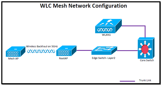
Our main aim is to force clients to be on a particular controller regardless of the controller they access the wireless network from. As per my Topology client connects to AP001 which is connected to WLC2 and traffic is tunneled back to WLC1, client must get IP from VLAN 192.

Autoanchor1

WLC2 (Foreign) Configuration:

Step1: Create a WLAN (In my example: RSCCIEW)

Step2: Assign to Management interface and choose the security to webauth.

Autoanchor2

Step3: Add WLC1 to its mobility list

Autoanchor3

Step4: Go to WLAN tab and assign the ANCHOR WLC.

Autoanchor4

In this case we assign the ANCHOR WLC to WLC1:

Autoanchor5

WLC1 (ANCHOR) Configuration:

Step1: Create the same WLAN as we did for WLC2 (Foreign)

Step2: Assign the interface (guest), except this everything should be same as WLC2.

Autoanchor6

Step3: Add WLC2 to its mobility list

Autoanchor7

Step4: Go to WLAN tab and assign the ANCHOR WLC.

Autoanchor8

In this case we will assign the ANCHOW WLC IP to local.

Autoanchor9

That’s all about configuration, Lets jump for verification:

From WLC2 (Foreign WLC)

Autoanchor10

From WLC1 (ANCHOR WLC) before webauth authentication.

Autoanchor11

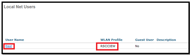
Now create a Local net user for testing

Autoanchor12

From WLC1 (ANCHOR WLC) After webauth authentication.

Autoanchor13

Here are the complete logs from WLC1 CLI:

(WLC1) >debug client  54:26:96:3e:4b:ee
(WLC1) >*mmListen: Nov 07 10:05:04.763: 54:26:96:3e:4b:ee Adding mobile on Remote AP 00:00:00:00:00:00(0)
 *mmListen: Nov 07 10:05:04.763: 54:26:96:3e:4b:ee override for default ap group, marking intgrp NULL
 *mmListen: Nov 07 10:05:04.764: 54:26:96:3e:4b:ee Applying Interface policy on Mobile, role Unassociated. Ms NAC State 2 Quarantine Vlan 0 Access Vlan 0
 *mmListen: Nov 07 10:05:04.764: 54:26:96:3e:4b:ee Re-applying interface policy for client
 *mmListen: Nov 07 10:05:04.764: 54:26:96:3e:4b:ee 0.0.0.0 START (0) Changing IPv4 ACL 'none' (ACL ID 255) ===> 'none' (ACL ID 255) --- (caller apf_policy.c:2219)
 *mmListen: Nov 07 10:05:04.764: 54:26:96:3e:4b:ee 0.0.0.0 START (0) Changing IPv6 ACL 'none' (ACL ID 255) ===> 'none' (ACL ID 255) --- (caller apf_policy.c:2240)
 *mmListen: Nov 07 10:05:04.764: 54:26:96:3e:4b:ee apfApplyWlanPolicy: Apply WLAN Policy over PMIPv6 Client Mobility Type
 *mmListen: Nov 07 10:05:04.764: 54:26:96:3e:4b:ee override from intf group to an intf for roamed client, removing intf group from mscb
 *mmListen: Nov 07 10:05:04.764: 54:26:96:3e:4b:ee Applying Interface policy on Mobile, role Unassociated. Ms NAC State 2 Quarantine Vlan 0 Access Vlan 192
 *mmListen: Nov 07 10:05:04.764: 54:26:96:3e:4b:ee Re-applying interface policy for client
 *mmListen: Nov 07 10:05:04.764: 54:26:96:3e:4b:ee 0.0.0.0 START (0) Changing IPv4 ACL 'none' (ACL ID 255) ===> 'none' (ACL ID 255) --- (caller apf_policy.c:2219)
 *mmListen: Nov 07 10:05:04.764: 54:26:96:3e:4b:ee 0.0.0.0 START (0) Changing IPv6 ACL 'none' (ACL ID 255) ===> 'none' (ACL ID 255) --- (caller apf_policy.c:2240)
 *mmListen: Nov 07 10:05:04.764: 54:26:96:3e:4b:ee 0.0.0.0 START (0) Initializing policy
 *mmListen: Nov 07 10:05:04.764: 54:26:96:3e:4b:ee 0.0.0.0 START (0) Change state to AUTHCHECK (2) last state START (0)
 *mmListen: Nov 07 10:05:04.764: 54:26:96:3e:4b:ee 0.0.0.0 AUTHCHECK (2) Change state to L2AUTHCOMPLETE (4) last state AUTHCHECK (2)
 *mmListen: Nov 07 10:05:04.764: 54:26:96:3e:4b:ee 0.0.0.0 L2AUTHCOMPLETE (4) Change state to DHCP_REQD (7) last state L2AUTHCOMPLETE (4)
 *mmListen: Nov 07 10:05:04.764: 54:26:96:3e:4b:ee Resetting web IPv4 acl from 255 to 255
 *mmListen: Nov 07 10:05:04.764: 54:26:96:3e:4b:ee Resetting web IPv4 Flex acl from 65535 to 65535
 *mmListen: Nov 07 10:05:04.764: 54:26:96:3e:4b:ee Stopping deletion of Mobile Station: (callerId: 53)
 *mmListen: Nov 07 10:05:04.764: 54:26:96:3e:4b:ee 0.0.0.0 DHCP_REQD (7) State Update from Mobility-Incomplete to Mobility-Complete, mobility role=ExpAnchor, client state=APF_MS_STATE_ASSOCIATED
 *mmListen: Nov 07 10:05:04.764: 54:26:96:3e:4b:ee 0.0.0.0 DHCP_REQD (7) Change state to DHCP_REQD (7) last state DHCP_REQD (7)
 *mmListen: Nov 07 10:05:04.764: 54:26:96:3e:4b:ee 0.0.0.0 DHCP_REQD (7) pemAdvanceState2 5761, Adding TMP rule
 *mmListen: Nov 07 10:05:04.764: 54:26:96:3e:4b:ee 0.0.0.0 DHCP_REQD (7) Adding Fast Path rule
 type = Airespace AP - Learn IP address
 on AP 00:00:00:00:00:00, slot 0, interface = 13, QOS = 0
 IPv4 ACL ID = 255, IP
 *mmListen: Nov 07 10:05:04.765: 54:26:96:3e:4b:ee 0.0.0.0 DHCP_REQD (7) Fast Path rule (contd...) 802.1P = 0, DSCP = 0, TokenID = 15206  Local Bridging Vlan = 192, Local Bridging intf id = 13
 *mmListen: Nov 07 10:05:04.765: 54:26:96:3e:4b:ee 0.0.0.0 DHCP_REQD (7) Successfully plumbed mobile rule (IPv4 ACL ID 255, IPv6 ACL ID 255, L2 ACL ID 255)
 *pemReceiveTask: Nov 07 10:05:04.767: 54:26:96:3e:4b:ee Set bi-dir guest tunnel for 54:26:96:3e:4b:ee as in Export Anchor role
 *pemReceiveTask: Nov 07 10:05:04.767: 54:26:96:3e:4b:ee 0.0.0.0 Added NPU entry of type 9, dtlFlags 0x4
 *pemReceiveTask: Nov 07 10:05:04.767: 54:26:96:3e:4b:ee Sent an XID frame
 *DHCP Socket Task: Nov 07 10:05:06.583: 54:26:96:3e:4b:ee DHCP received op BOOTREQUEST (1) (len 308,vlan 80, port 13, encap 0xec05)
 *DHCP Socket Task: Nov 07 10:05:06.583: 54:26:96:3e:4b:ee DHCP (encap type 0xec05) mstype 3ff:ff:ff:ff:ff:ff
 *DHCP Socket Task: Nov 07 10:05:06.583: 54:26:96:3e:4b:ee DHCP selecting relay 1 - control block settings:
 dhcpServer: 0.0.0.0, dhcpNetmask: 0.0.0.0,
 dhcpGateway: 0.0.0.0, dhcpRelay: 0.0.0.0  VLAN: 0
 *DHCP Socket Task: Nov 07 10:05:06.583: 54:26:96:3e:4b:ee DHCP selected relay 1 - 192.168.80.1 (local address 192.168.99.1, gateway 192.168.99.254, VLAN 192, port 13)
 *DHCP Socket Task: Nov 07 10:05:06.583: 54:26:96:3e:4b:ee DHCP transmitting DHCP REQUEST (3)
 *DHCP Socket Task: Nov 07 10:05:06.583: 54:26:96:3e:4b:ee DHCP   op: BOOTREQUEST, htype: Ethernet, hlen: 6, hops: 1
 *DHCP Socket Task: Nov 07 10:05:06.583: 54:26:96:3e:4b:ee DHCP   xid: 0x761692a1 (1981190817), secs: 5, flags: 0
 *DHCP Socket Task: Nov 07 10:05:06.583: 54:26:96:3e:4b:ee DHCP   chaddr: 54:26:96:3e:4b:ee
 *DHCP Socket Task: Nov 07 10:05:06.583: 54:26:96:3e:4b:ee DHCP   ciaddr: 0.0.0.0,  yiaddr: 0.0.0.0
 *DHCP Socket Task: Nov 07 10:05:06.583: 54:26:96:3e:4b:ee DHCP   siaddr: 0.0.0.0,  giaddr: 192.168.99.1
 *DHCP Socket Task: Nov 07 10:05:06.583: 54:26:96:3e:4b:ee DHCP   requested ip: 192.168.99.5
 *DHCP Socket Task: Nov 07 10:05:06.583: 54:26:96:3e:4b:ee DHCP selecting relay 2 - control block settings:
 dhcpServer: 0.0.0.0, dhcpNetmask: 0.0.0.0,
 dhcpGateway: 0.0.0.0, dhcpRelay: 192.168.99.1  VLAN: 192
 *DHCP Socket Task: Nov 07 10:05:06.583: 54:26:96:3e:4b:ee DHCP selected relay 2 - NONE (server address 0.0.0.0,local address 0.0.0.0, gateway 192.168.99.254, VLAN 192, port 13)
 *DHCP Proxy Task: Nov 07 10:05:06.586: 54:26:96:3e:4b:ee DHCP received op BOOTREPLY (2) (len 572,vlan 0, port 0, encap 0x0)
 *DHCP Proxy Task: Nov 07 10:05:06.586: 54:26:96:3e:4b:ee DHCP setting server from ACK (server 192.168.80.1, yiaddr 192.168.99.5)
 *DHCP Proxy Task: Nov 07 10:05:06.586: 54:26:96:3e:4b:ee Static IP client associated to interface guest which can support client subnet.
 *DHCP Proxy Task: Nov 07 10:05:06.586: 54:26:96:3e:4b:ee 192.168.99.5 DHCP_REQD (7) Change state to WEBAUTH_REQD (8) last state DHCP_REQD (7)
 *DHCP Proxy Task: Nov 07 10:05:06.586: 54:26:96:3e:4b:ee 192.168.99.5 WEBAUTH_REQD (8) pemAdvanceState2 6671, Adding TMP rule
 *DHCP Proxy Task: Nov 07 10:05:06.586: 54:26:96:3e:4b:ee 192.168.99.5 WEBAUTH_REQD (8) Replacing Fast Path rule
 type = Airespace AP Client - ACL passthru
 on AP 00:00:00:00:00:00, slot 0, interface = 13, QOS = 0
 IPv4 ACL
 *DHCP Proxy Task: Nov 07 10:05:06.586: 54:26:96:3e:4b:ee 192.168.99.5 WEBAUTH_REQD (8) Fast Path rule (contd...) 802.1P = 0, DSCP = 0, TokenID = 15206  Local Bridging Vlan = 192, Local Bridging intf id = 13
 *DHCP Proxy Task: Nov 07 10:05:06.586: 54:26:96:3e:4b:ee 192.168.99.5 WEBAUTH_REQD (8) Successfully plumbed mobile rule (IPv4 ACL ID 255, IPv6 ACL ID 255, L2 ACL ID 255)
 *DHCP Proxy Task: Nov 07 10:05:06.586: 54:26:96:3e:4b:ee Plumbing web-auth redirect rule due to user logout
 *DHCP Proxy Task: Nov 07 10:05:06.586: 54:26:96:3e:4b:ee Assigning Address 192.168.99.5 to mobile
 *DHCP Proxy Task: Nov 07 10:05:06.586: 54:26:96:3e:4b:ee DHCP success event for client. Clearing dhcp failure count for interface guest.
 *DHCP Proxy Task: Nov 07 10:05:06.586: 54:26:96:3e:4b:ee DHCP success event for client. Clearing dhcp failure count for interface guest.
 *DHCP Proxy Task: Nov 07 10:05:06.586: 54:26:96:3e:4b:ee DHCP transmitting DHCP ACK (5)
 *DHCP Proxy Task: Nov 07 10:05:06.586: 54:26:96:3e:4b:ee DHCP   op: BOOTREPLY, htype: Ethernet, hlen: 6, hops: 0
 *DHCP Proxy Task: Nov 07 10:05:06.586: 54:26:96:3e:4b:ee DHCP   xid: 0x761692a1 (1981190817), secs: 0, flags: 0
 *DHCP Proxy Task: Nov 07 10:05:06.586: 54:26:96:3e:4b:ee DHCP   chaddr: 54:26:96:3e:4b:ee
 *DHCP Proxy Task: Nov 07 10:05:06.587: 54:26:96:3e:4b:ee DHCP   ciaddr: 0.0.0.0,  yiaddr: 192.168.99.5
 *DHCP Proxy Task: Nov 07 10:05:06.587: 54:26:96:3e:4b:ee DHCP   siaddr: 0.0.0.0,  giaddr: 0.0.0.0
 *DHCP Proxy Task: Nov 07 10:05:06.587: 54:26:96:3e:4b:ee DHCP   server id: 1.1.1.1  rcvd server id: 192.168.80.1
 *pemReceiveTask: Nov 07 10:05:06.589: 54:26:96:3e:4b:ee Set bi-dir guest tunnel for 54:26:96:3e:4b:ee as in Export Anchor role
 *pemReceiveTask: Nov 07 10:05:06.589: 54:26:96:3e:4b:ee 192.168.99.5 Added NPU entry of type 2, dtlFlags 0x4
 *pemReceiveTask: Nov 07 10:05:06.589: 54:26:96:3e:4b:ee Sent an XID frame
 *ewmwebWebauth1: Nov 07 10:05:32.617: 54:26:96:3e:4b:ee Username entry (ttest) created for mobile, length = 5
 *ewmwebWebauth1: Nov 07 10:05:32.617: 54:26:96:3e:4b:ee Username entry (ttest) created in mscb for mobile, length = 5
 *ewmwebWebauth1: Nov 07 10:05:32.618: 54:26:96:3e:4b:ee 192.168.99.5 WEBAUTH_REQD (8) Change state to WEBAUTH_NOL3SEC (14) last state WEBAUTH_REQD (8)
 *ewmwebWebauth1: Nov 07 10:05:32.618: 54:26:96:3e:4b:ee apfMsRunStateInc
 *ewmwebWebauth1: Nov 07 10:05:32.618: 54:26:96:3e:4b:ee 192.168.99.5 WEBAUTH_NOL3SEC (14) Change state to RUN (20) last state WEBAUTH_NOL3SEC (14)
 *ewmwebWebauth1: Nov 07 10:05:32.618: 54:26:96:3e:4b:ee Session Timeout is 0 - not starting session timer for the mobile
 *ewmwebWebauth1: Nov 07 10:05:32.618: 54:26:96:3e:4b:ee 192.168.99.5 RUN (20) Reached PLUMBFASTPATH: from line 6559
 *ewmwebWebauth1: Nov 07 10:05:32.618: 54:26:96:3e:4b:ee 192.168.99.5 RUN (20) Replacing Fast Path rule
 type = Airespace AP Client
 on AP 00:00:00:00:00:00, slot 0, interface = 13, QOS = 0
 IPv4 ACL ID = 255, IPv6 ACL ID
 *ewmwebWebauth1: Nov 07 10:05:32.618: 54:26:96:3e:4b:ee 192.168.99.5 RUN (20) Fast Path rule (contd...) 802.1P = 0, DSCP = 0, TokenID = 15206  Local Bridging Vlan = 192, Local Bridging intf id = 13
 *ewmwebWebauth1: Nov 07 10:05:32.618: 54:26:96:3e:4b:ee 192.168.99.5 RUN (20) Successfully plumbed mobile rule (IPv4 ACL ID 255, IPv6 ACL ID 255, L2 ACL ID 255)
 *pemReceiveTask: Nov 07 10:05:32.626: 54:26:96:3e:4b:ee Set bi-dir guest tunnel for 54:26:96:3e:4b:ee as in Export Anchor role
 *pemReceiveTask: Nov 07 10:05:32.626: 54:26:96:3e:4b:ee 192.168.99.5 Added NPU entry of type 1, dtlFlags 0x4
 *pemReceiveTask: Nov 07 10:05:32.627: 54:26:96:3e:4b:ee Sending a gratuitous ARP for 192.168.99.5, VLAN Id 192

Here are the complete logs from WLC2 CLI:

(WLC2) >debug client  54:26:96:3e:4b:ee
(WLC2) >*pemReceiveTask: Nov 07 10:00:16.787: 54:26:96:3e:4b:ee 0.0.0.0 Removed NPU entry.
 *apfMsConnTask_0: Nov 07 10:04:31.368: 54:26:96:3e:4b:ee Adding mobile on LWAPP AP 00:22:bd:98:3a:30(1)
 *apfMsConnTask_0: Nov 07 10:04:31.368: 54:26:96:3e:4b:ee Association received from mobile on AP 00:22:bd:98:3a:30
 *apfMsConnTask_0: Nov 07 10:04:31.368: 54:26:96:3e:4b:ee 0.0.0.0 START (0) Changing ACL 'none' (ACL ID 0) ===> 'none' (ACL ID 255) --- (caller apf_policy.c:1633)
 *apfMsConnTask_0: Nov 07 10:04:31.368: 54:26:96:3e:4b:ee Applying site-specific IPv6 override for station 54:26:96:3e:4b:ee - vapId 4, site 'default-group', interface 'management'
 *apfMsConnTask_0: Nov 07 10:04:31.368: 54:26:96:3e:4b:ee Applying IPv6 Interface Policy for station 54:26:96:3e:4b:ee - vlan 80, interface id 0, interface 'management'
 *apfMsConnTask_0: Nov 07 10:04:31.368: 54:26:96:3e:4b:ee STA - rates (8): 140 18 152 36 176 72 96 108 0 0 0 0 0 0 0 0
 *apfMsConnTask_0: Nov 07 10:04:31.368: 54:26:96:3e:4b:ee 0.0.0.0 START (0) Initializing policy
 *apfMsConnTask_0: Nov 07 10:04:31.368: 54:26:96:3e:4b:ee 0.0.0.0 START (0) Change state to AUTHCHECK (2) last state AUTHCHECK (2)
 *apfMsConnTask_0: Nov 07 10:04:31.368: 54:26:96:3e:4b:ee 0.0.0.0 AUTHCHECK (2) Change state to L2AUTHCOMPLETE (4) last state L2AUTHCOMPLETE (4)
 *apfMsConnTask_0: Nov 07 10:04:31.368: 54:26:96:3e:4b:ee 0.0.0.0 L2AUTHCOMPLETE (4) DHCP Not required on AP 00:22:bd:98:3a:30 vapId 4 apVapId 4for this client
 *apfMsConnTask_0: Nov 07 10:04:31.369: 54:26:96:3e:4b:ee Not Using WMM Compliance code qosCap 00
 *apfMsConnTask_0: Nov 07 10:04:31.369: 54:26:96:3e:4b:ee 0.0.0.0 L2AUTHCOMPLETE (4) Plumbed mobile LWAPP rule on AP 00:22:bd:98:3a:30 vapId 4 apVapId 4
 *apfMsConnTask_0: Nov 07 10:04:31.369: 54:26:96:3e:4b:ee 0.0.0.0 L2AUTHCOMPLETE (4) Change state to DHCP_REQD (7) last state DHCP_REQD (7)
 *apfMsConnTask_0: Nov 07 10:04:31.369: 54:26:96:3e:4b:ee apfMsAssoStateInc
 *apfMsConnTask_0: Nov 07 10:04:31.369: 54:26:96:3e:4b:ee apfPemAddUser2 (apf_policy.c:223) Changing state for mobile 54:26:96:3e:4b:ee on AP 00:22:bd:98:3a:30 from Idle to Associated
 *apfMsConnTask_0: Nov 07 10:04:31.369: 54:26:96:3e:4b:ee Stopping deletion of Mobile Station: (callerId: 48)
 *apfMsConnTask_0: Nov 07 10:04:31.369: 54:26:96:3e:4b:ee Sending Assoc Response to station on BSSID 00:22:bd:98:3a:30 (status 0) ApVapId 4 Slot 1
 *apfMsConnTask_0: Nov 07 10:04:31.369: 54:26:96:3e:4b:ee apfProcessAssocReq (apf_80211.c:5276) Changing state for mobile 54:26:96:3e:4b:ee on AP 00:22:bd:98:3a:30 from Associated to Associated
 *DHCP Socket Task: Nov 07 10:04:31.722: 54:26:96:3e:4b:ee DHCP received op BOOTREQUEST (1) (len 308,vlan 80, port 1, encap 0xec03)
 *DHCP Socket Task: Nov 07 10:04:31.723: 54:26:96:3e:4b:ee DHCP dropping packet due to ongoing mobility handshake exchange, (siaddr 0.0.0.0,  mobility state = 'apfMsMmQueryRequested'
 *DHCP Socket Task: Nov 07 10:04:33.461: 54:26:96:3e:4b:ee DHCP received op BOOTREQUEST (1) (len 308,vlan 80, port 1, encap 0xec03)
 *DHCP Socket Task: Nov 07 10:04:33.461: 54:26:96:3e:4b:ee DHCP dropping packet due to ongoing mobility handshake exchange, (siaddr 0.0.0.0,  mobility state = 'apfMsMmQueryRequested'
 *apfReceiveTask: Nov 07 10:04:34.238: 54:26:96:3e:4b:ee 0.0.0.0 DHCP_REQD (7) State Update from Mobility-Incomplete to Mobility-Complete, mobility role=ExpForeign, client state=APF_MS_STATE_ASSOCIATED
 *apfReceiveTask: Nov 07 10:04:34.238: 54:26:96:3e:4b:ee apfMsRunStateInc
 *apfReceiveTask: Nov 07 10:04:34.238: 54:26:96:3e:4b:ee 0.0.0.0 DHCP_REQD (7) Change state to RUN (20) last state RUN (20)
 *apfReceiveTask: Nov 07 10:04:34.240: 54:26:96:3e:4b:ee 0.0.0.0 RUN (20) Reached PLUMBFASTPATH: from line 4563
 *apfReceiveTask: Nov 07 10:04:34.240: 54:26:96:3e:4b:ee 0.0.0.0 RUN (20) Adding Fast Path rule
 type = Airespace AP Client
 on AP 00:22:bd:98:3a:30, slot 1, interface = 1, QOS = 0
 ACL Id = 255, Jumbo Frames = NO
 *apfReceiveTask: Nov 07 10:04:34.240: 54:26:96:3e:4b:ee 0.0.0.0 RUN (20) Fast Path rule (contd...) 802.1P = 0, DSCP = 0, TokenID = 1506  IPv6 Vlan = 80, IPv6 intf id = 0
 *apfReceiveTask: Nov 07 10:04:34.240: 54:26:96:3e:4b:ee 0.0.0.0 RUN (20) Successfully plumbed mobile rule (ACL ID 255)
 *pemReceiveTask: Nov 07 10:04:34.243: 54:26:96:3e:4b:ee Set bi-dir guest tunnel for 54:26:96:3e:4b:ee as in Export Foreign role
 *pemReceiveTask: Nov 07 10:04:34.256: 54:26:96:3e:4b:ee 0.0.0.0 Added NPU entry of type 1, dtlFlags 0x4
 *DHCP Socket Task: Nov 07 10:04:36.055: 54:26:96:3e:4b:ee DHCP received op BOOTREQUEST (1) (len 308,vlan 80, port 1, encap 0xec03)
 *DHCP Socket Task: Nov 07 10:04:36.055: 54:26:96:3e:4b:ee DHCP processing DHCP REQUEST (3)
 *DHCP Socket Task: Nov 07 10:04:36.055: 54:26:96:3e:4b:ee DHCP   op: BOOTREQUEST, htype: Ethernet, hlen: 6, hops: 0
 *DHCP Socket Task: Nov 07 10:04:36.055: 54:26:96:3e:4b:ee DHCP   xid: 0x761692a1 (1981190817), secs: 1280, flags: 0
 *DHCP Socket Task: Nov 07 10:04:36.055: 54:26:96:3e:4b:ee DHCP   chaddr: 54:26:96:3e:4b:ee
 *DHCP Socket Task: Nov 07 10:04:36.055: 54:26:96:3e:4b:ee DHCP   ciaddr: 0.0.0.0,  yiaddr: 0.0.0.0
 *DHCP Socket Task: Nov 07 10:04:36.056: 54:26:96:3e:4b:ee DHCP   siaddr: 0.0.0.0,  giaddr: 0.0.0.0
 *DHCP Socket Task: Nov 07 10:04:36.056: 54:26:96:3e:4b:ee DHCP   requested ip: 192.168.99.5
 *DHCP Socket Task: Nov 07 10:04:36.056: 54:26:96:3e:4b:ee DHCP successfully bridged packet to EoIP tunnel
 *DHCP Socket Task: Nov 07 10:04:36.060: 54:26:96:3e:4b:ee DHCP received op BOOTREPLY (2) (len 312,vlan 80, port 1, encap 0xec05)
 *DHCP Socket Task: Nov 07 10:04:36.060: 54:26:96:3e:4b:ee DHCP processing DHCP ACK (5)
 *DHCP Socket Task: Nov 07 10:04:36.060: 54:26:96:3e:4b:ee DHCP   op: BOOTREPLY, htype: Ethernet, hlen: 6, hops: 0
 *DHCP Socket Task: Nov 07 10:04:36.061: 54:26:96:3e:4b:ee DHCP   xid: 0x761692a1 (1981190817), secs: 0, flags: 0
 *DHCP Socket Task: Nov 07 10:04:36.061: 54:26:96:3e:4b:ee DHCP   chaddr: 54:26:96:3e:4b:ee
 *DHCP Socket Task: Nov 07 10:04:36.061: 54:26:96:3e:4b:ee DHCP   ciaddr: 0.0.0.0,  yiaddr: 192.168.99.5
 *DHCP Socket Task: Nov 07 10:04:36.061: 54:26:96:3e:4b:ee DHCP   siaddr: 0.0.0.0,  giaddr: 0.0.0.0
 *DHCP Socket Task: Nov 07 10:04:36.061: 54:26:96:3e:4b:ee DHCP   server id: 1.1.1.1  rcvd server id: 1.1.1.1
 *DHCP Socket Task: Nov 07 10:04:36.062: 54:26:96:3e:4b:ee 192.168.99.5 RUN (20) DHCP Address Re-established
 *DHCP Socket Task: Nov 07 10:04:36.062: 54:26:96:3e:4b:ee Assigning Address 192.168.99.5 to mobile
 *DHCP Socket Task: Nov 07 10:04:36.062: 54:26:96:3e:4b:ee DHCP success event for client. Clearing dhcp failure count for interface management.

Logging configuration on WLC

In this post we will learn how to configure WLC for logging option. Logs are always good to have while troubleshooting any issue.

Console logging: By default, the devices send all log messages to its console port. Hence only the users that are physically connected to the router console port can view these messages.

Terminal logging: It is similar to console logging, but it displays log messages to the devices VTY (Telnet or SSH) lines instead. This is not enabled by default

Buffered logging: This type of logging uses device RAM for storing log messages. Buffer has a fixed size to ensure that the log will not deplete valuable system memory.

Syslog Server logging: The device can use syslog to forward log messages to external syslog servers for storage. This type of logging is not enabled by default.

SNMP trap logging: The device is able to use SNMP traps to send log messages to an external SNMP server.

What we can configure:

Syslog:

  • Syslog host
  • Syslog facility
  • Syslog level

Message Log:

  • Buffered Log Level
  • Console Log Level
  • File Info
  • Trace Info

Syslog configuration:

Screenshot from WLC: Management > Logs > Config.

Logg1

Via GUI we have only two options for syslog configuration but via CLI we have four options:

Via GUI:

To configure syslog in cisco WLC we have to go Management > Logs > Config option.

  1. Put the IP of the syslog host where we want to send it and click on Add.
  2. Then select the syslog level from drop down box.
  3. Select the Syslog facility from drop down box.

Logg2

*** If we set a syslog level, only those messages whose severity is equal to or less than that level are sent to the syslog server.

*** After code 5.x, it’s possible to send the logging to multiple syslog servers.

Via CLI:

(WLAN1) >config logging syslog ?
 facility       Set facility for outgoing syslog mesages to remote host.
 host           Configure remote hosts for sending syslog mesages.
 level          Set severity level for filtering syslog mesages to remote host.
 tls            Configure sending syslog messages over tls.
(WLAN1) >config logging syslog host 192.168.10.1
 System logs will be sent to 192.168.10.1 from now on
(WLAN1) >config logging syslog host ?
 <A.B.C.D>      dotted IP address of the remote host.
(WLAN1) >config logging syslog facility ?
 auth-private   Authorization system (private).
 authorization  Authorization system.
 cron           Cron/at facility.
 daemon         System daemons.
 ftp            FTP daemon.
 kern           Kernel.
 local0         Local use.
 local1         Local use.
 local2         Local use.
 local3         Local use.
 local4         Local use.
 local5         Local use.
 local6         Local use.
 local7         Local use.
 lpr            Line printer system.
 mail           Mail system.
 news           USENET news.
 sys12          System use.
 sys13          System use.
 sys14          System use.
 sys15          System use.
 syslog         Syslog itself.
 user           User process.
 uucp           Unix-to-Unix copy system.
(WLAN1) >config logging syslog facility local?
 local0         local1         local2         local3         local4
 local5         local6         local7
(WLAN1) >config logging syslog facility local4
(WLAN1) >config logging syslog level ?
 <0-7>          Set syslog message logging message severity level.
 alerts         Set syslog message logging severity to 'alerts' (severity 1).
 critical       Set syslog message logging severity to 'critical' (severity 2).
 debugging      Set syslog message logging severity to 'debugging' (severity 7).
 emergencies    Set syslog message logging severity to 'emergencies' (severity 0).
 errors         Set syslog message logging severity to 'errors' (severity 3).
 informational  Set syslog message logging severity to 'informational' (severity 6).
 notifications  Set syslog message logging severity to 'notifications' (severity 5).
 warnings       Set syslog message logging severity to 'warnings' (severity 4).
(WLAN1) >config logging syslog level warnings
(WLAN1) >config logging syslog tls ?
 enable         Enable logging message to syslog over tls.
 disable        Disable logging message to syslog over tls.

***Note: When we are configuring syslogs for APs, it is always recommended to do it after the APs have joined up to the WLCs to ensure that they get the configurations.

Syslog configuration for APs via WLC CLI interface.

(WLAN1) >config ap syslog host ?
 global         Configures the global system logging host for all Cisco AP
 specific       Configures the system logging host for a specific Cisco AP.
(WLAN1) >config ap syslog host specific ?
 <ap-name>      Specify the name of the specific Cisco AP.
(WLAN1) >config ap syslog host specific AP001 ?
 <a.b.c.d>      IP address of the system logging host for the specified Cisco AP
(WLAN1) >config ap syslog host specific AP001 192.168.10.1
 (WLAN1) >config ap logging ?
 syslog         Set Ap logging syslog level.
(WLAN1) >config ap logging syslog ?
 level          Syslog level.
 facility       Facility level.
(WLAN1) >config ap logging syslog level ?
 alerts         Logging severity level 1.
 critical       Logging severity level 2.
 debugging      Logging severity level 7.
 emergencies    Logging severity level 0.
 errors         Logging severity level 3.
 informational  Logging severity level 6.
 notifications  Logging severity level 5.
 warnings       Logging severity level 4.
(WLAN1) >config ap logging syslog level warnings ?
 <Cisco AP>     Enter the name of the Cisco AP.
 all            Applies the settings to all APs.
(WLAN1) >config ap logging syslog level warnings all
(WLAN1) >config ap logging syslog facility ?
 auth           Authorization system.
 cron           Cron/at facility.
 daemon         System daemons.
 kern           Kernel.
 local0         Local use.
 local1         Local use.
 local2         Local use.
 local3         Local use.
 local4         Local use.
 local5         Local use.
 local6         Local use.
 local7         Local use.
 lpr            Line printer system.
 mail           Mail system.
 news           USENET news.
 sys10          System use.
 sys11          System use.
 sys12          System use.
 sys13          System use.
 sys14          System use.
 sys9           System use.
 syslog         Syslog itself.
 user           User process.
 uucp           Unix-to-Unix copy system.
(WLAN1) >config ap logging syslog facility lo?
 local0         local1         local2         local3         local4
 local5         local6         local7
(WLAN1) >config ap logging syslog facility loc?
 local0         local1         local2         local3         local4
 local5         local6         local7
(WLAN1) >config ap logging syslog facility local4 ?
 <Cisco AP>     Enter the name of the Cisco AP.
 all            Applies the settings to all APs.
(WLAN1) >config ap logging syslog facility local4 all

Message Log Configuration:

Via GUI:

Buffered log level:

Logg3

Console Log level:

Logg4

Via CLI:

Buffered log level:

(WLAN1) >config logging  ?
 buffered       Set buffered logging parameters.
 console        Set console logging parameters.
 debug          Set debug message logging parameters.
 exception      Limit size of exception flush output.
 fileinfo       Set source file information logging parameters.
 syslog         Configure parameters for outgoing syslog mesages.
 traceinfo      Set traceback information logging parameters.
 (WLAN1) >config logging buffered ?
 <0-7>          Set buffer logging message severity level.
 alerts         Set buffer logging severity to 'alerts' (severity 1).
 critical       Set buffer logging severity to 'critical' (severity 2).
 debugging      Set buffer logging severity to 'debugging' (severity 7).
 emergencies    Set buffer logging severity to 'emergencies' (severity 0).
 errors         Set buffer logging severity to 'errors' (severity 3).
 informational  Set buffer logging severity to 'informational' (severity 6).
 notifications  Set buffer logging severity to 'notifications' (severity 5).
 warnings       Set buffer logging severity to 'warnings' (severity 4).
 (WLAN1) >config logging buffered warnings

Console Log level:

(WLAN1) >config logging console ?
 <0-7>          Set console logging message severity level.
 alerts         Set console logging severity to 'alerts' (severity 1).
 critical       Set console logging severity to 'critical' (severity 2).
 debugging      Set console logging severity to 'debugging' (severity 7).
 disable        Disable console logging.
 emergencies    Set console logging severity to 'emergencies' (severity 0).
 errors         Set console logging severity to 'errors' (severity 3).
 informational  Set console logging severity to 'informational' (severity 6).
 notifications  Set console logging severity to 'notifications' (severity 5).
 warnings       Set console logging severity to 'warnings' (severity 4).
 (WLAN1) >config logging console warnings

To verify the syslog configuration, use the show logging command from the WLC CLI:

(WLAN1) >show logging
 Logging to buffer :
 - Logging of system messages to buffer :
 - Logging filter level.......................... warnings
 - Number of system messages logged.............. 61
 - Number of system messages dropped............. 1139290
 - Logging of debug messages to buffer ........... Disabled
 - Number of debug messages logged............... 0
 - Number of debug messages dropped.............. 0
 Logging to console :
 - Logging of system messages to console :
 - Logging filter level.......................... warnings
 - Number of system messages logged.............. 0
 - Number of system messages dropped............. 1139351
 - Logging of debug messages to console .......... Enabled
 - Number of debug messages logged............... 0
 - Number of debug messages dropped.............. 0
 Logging to syslog :
 - Syslog facility................................ local4
 - Logging of system messages to syslog :
 - Logging filter level.......................... warnings
 - Number of system messages logged.............. 61
 - Number of system messages dropped............. 1139290
 - Logging of debug messages to syslog ........... Disabled
 - Number of debug messages logged............... 0
 - Number of debug messages dropped.............. 0
 - Number of remote syslog hosts.................. 1
 - syslog over tls................................ Disabled
 - Host 0....................................... 192.168.10.1

To view the message logs use this command from WLC CLI:

(WLAN1) >show msglog

Autonomous AP Logging:

Example:

  • AAPs send syslogs to server 192.168.10.1
  • Send notifications or higher.
  • Use facility local7

Use these commands to configure:

Conf t
 logging trap notifications
 logging facility local7
 logging 192.168.10.1


Verification for AAP:

AAP#show logging
 Syslog logging: enabled (1 messages dropped, 19 messages rate-limited,
 0 flushes, 0 overruns, xml disabled, filtering disabled)
 Console logging: level debugging, 235 messages logged, xml disabled, filtering disabled
 Monitor logging: level debugging, 0 messages logged, xml disabled, filtering disabled
 Buffer logging: level debugging, 252 messages logged, xml disabled, filtering disabled
 Logging Exception size (4096 bytes)
 Count and timestamp logging messages: disabled
 Trap logging: level notifications, 127 message lines logged
 Logging to 192.168.10.1(global) (udp port 514, audit disabled, link up), 127 message lines logged, xml disabled, filtering disabled
AAP# show run | in facil
 logging facility local7

Multicast in Mesh Mode

In this post we will learn about multicast in Mesh environment.

It’s a big issue for mesh network if multicast packets are forwarded to all destinations result in overload the mesh Backhaul. The Main aim is to reduce the number of multicast packets on the backhaul.

There are three modes for multicast in mesh:

  1. Regular
  2. In Mode
  3. In-Out Mode

Regular: It’s the same as hub works to flood the packets means if a multicast packet received and subsequently flooded to all ports.

In Mode:

  • As name indicate its Very Restrictive mode
  • Means Way-up only.
  • Multicast packets that originated on a MAP Ethernet are sent to the MAPs parent or RAP only.
  • Multicast packets coming in from the parent to the MAP, is dropped.
  • Multicast packets coming in on the RAP Ethernet port is dropped by the RAP itself.
  • Multicast packets coming in over the air from the child send to the parent only.

In-Out Mode:

  • Mixed of regular and IN mode
  • IN-mode rules will apply for a packet going from MAP -> RAP -> RAP’s primary LAN
  • Regular mode rules apply for a packet going from Primary LAN -> RAP -> MAP direction

Configuration multicast mode on WLC for mesh AP:

(WLAN1) >config network multicast global enable
(WLAN1) >config mesh multicast ?
 in-only        Configure Mesh Multicast In Mode.
 in-out         Configure Mesh Multicast In-Out Mode.
 regular        Configure Mesh Multicast Regular Mode.
(WLAN1) >config mesh multicast in-out

More detail about Mesh AP detail:

http://dot11.info/index.php?title=Introduction_to_MESH#Multicast_over_Mesh

WLC Mesh Network Configuration

In this post we will learn about the configuration guide point to point wireless bridging using the Mesh Network solution from WLC.

This is my topology:

Mesh1

Right now I have both AP connected to WLC in local mode.

Remembering points:

  • An AP in mesh mode needs to be authorized to join a controller. So the first step is therefore to add there mac address.
  • Before converting to bridge mode we must add the mac address of the both APAP in Policies list or the MAC filtering list. From Security > AAA > AP Policies, click Add.
  • To configure Mesh, we will need to do multiple reboots of our APs. To reduce the number of reboots, configure all of the global Mesh settings first
  • Don’t use static IP address especially on MAP.

From Security > AAA > AP Policies, click Add.

Mesh2

Now place both AP into Bridge mode (just another name for Mesh mode).

LAP1:

Mesh3

LAP2:

Mesh4

After selection of Bridge mode we must apply it. Then both AP will reboot.

See the screenshot when both AP came as in Bridge Mode:

Mesh5

Once the AP reboots, a new MESH tab is available under:  Wireless > All APs, click on AP1 or AP2.

Mesh6

Here are few boxes which we should remember.

AP Role: Either RAP or MAP

Bridge Type: Indoor

Bridge Group Name (BGN): It’s like a workgroup name, allow the APs to know which AP are part of their group. (Here in my example we will take BGN as rscciew123)

Bridge Data Rates: Rate at which data is shared between the mesh access points. This is fixed for a whole network. Default data rate is 18 Mbps, which you should use for the backhaul. Valid data rates: for 802.11a: 6, 9, 12, 18, 24, 36, 48, and 54

Since AP2 will send its traffic through AP1, AP1 will be the RAP and AP2 will be the MAP. Don’t forget to configure an identical Bridge ID. (Otherwise leave it blank for both APs)

In Mesh tab, configure the rest of the AP settings.

  • Select RAP role to AP1 and assign BGN name (rscciew123)
  • Select MAP role to AP2 and assign BGN name (rscciew123)

And Apply. The APs will go through reboot again, and will take few minutes to rejoin to WLC.

*** MAPs use Adaptive Wireless Path Protocol (AWPP) to determine the best path through the mesh APs to their WLC. The protocol takes path decisions based on both link-quality and number of Mesh hops.

To prevent AP2 from simply connecting back up to the WLC through its wired port, Either place AP2 into VLAN 100(Not routable) or make the wired port shut for AP2, so that it has no path to the WLC except though its radios.

This is not mandatory- (When the APs come back up, AP1 will do another MAC auth. But AP2 will do a user auth. See the SNMP trap logs for the user name, and then create a local user with that name and make the password identical to the name.)We can see this error in trap log on WLC.

Now my Both AP is up.

Now check the status: Go to Wireless > All APs , far right on AP1 there is blue box ,click on that and select Neighbor Information

Mesh7

Mesh8

Verification:

We can also check from AP1 and AP2 CLI:

On AP1:

AP001#sh mesh status
 show MESH Status
 RootAP in state Maint
 Uplink Backbone: FastEthernet0,  hw FastEthernet0
 Configured BGN: rscciew123, Extended mode 0
 Children: Accept child
 rxNeighReq 187 rxNeighRsp 0 txNeighReq 0 txNeighRsp 187
 rxNeighRsp 653 txNeighUpd 3333
 nextchan 0 nextant 0 downAnt 0 downChan 0 curAnts 0
 nextNeigh 1, malformedNeighPackets 0,poorNeighSnr 0
 excludedPackets 0,insufficientMemory 0, authenticationFailures 0
 Parent Changes 1, Neighbor Timeouts 0
 Vector through XXXX.XX96.3404:
 Vector ease 1 -1, FWD: XXXX.XX96.3404
AP001#sh mesh adjacency child
 show MESH Adjacency Child
 ADJ 1 Identity YYYY.YY03.e31c MA: 003a.9914.137f ver 0x20 minver 0x0 on device Dot11Radio:1 txpkts 754 txretries 420
 Flags: CHILD BEACON
 worstDv 255 Ant 0, channel 64, biters 0, ppiters 10, fwd_state 3
 Numroutes 0, snr 0, snrUp 10 snrDown 0 linkSnr 0 blistExp 3 bliters 0
 adjustedEase 0 unadjustedEase 0 stickyEase 0 txParent 0 rxParent 0
 BGN rscciew123
 Vector through YYYY.YY03.e31c:
 Per antenna smoothed snr values: 0 0 0 0
 Subordinate neighbors: YYYY.YY03.e31c
 Hop-Count Extension: ON, Version: 1

On AP2:

AP002#sh mesh status
 show MESH Status
 MeshAP in state Maint
 Uplink Backbone: Virtual-Dot11Radio0,  hw Dot11Radio1
 Configured BGN: rscciew123, Extended mode 0
 Children: Accept child
 rxNeighReq 0 rxNeighRsp 213 txNeighReq 372 txNeighRsp 0
 rxNeighRsp 1094 txNeighUpd 966
 nextchan 0 nextant 0 downAnt 0 downChan 0 curAnts 0
 nextNeigh 3, malformedNeighPackets 0,poorNeighSnr 44
 excludedPackets 0,insufficientMemory 0, authenticationFailures 0
 Parent Changes 7, Neighbor Timeouts 0
 Vector through XXXX.XX96.3404:
 Vector ease 1 -1, FWD: XXXX.XX96.3404
AP002#sh mesh adjacency parent
 show MESH Adjacency Parent
 ADJ 1 Identity XXXX.XX96.3404 MA: 0022.bd98.3a3f ver 0x20 minver 0x20 on device Dot11Radio:1 txpkts 712 txretries 247
 Flags: UPDATED NEIGH PARENT BEACON
 worstDv 0 Ant 0, channel 64, biters 0, ppiters 10, fwd_state 3
 Numroutes 1, snr 0, snrUp 13 snrDown 10 linkSnr 9 blistExp 2 bliters 0
 adjustedEase 512 unadjustedEase 512 stickyEase 2048 txParent 349 rxParent 199
 Authentication: EAP, Encryption: AES-CCMP, Fwd-state: OPEN/CONTROL
 BGN rscciew123
 Vector through XXXX.XX96.3404:
 Vector ease 1 -1, FWD: XXXX.XX96.3404
 Per antenna smoothed snr values: 9 0 0 0
 Hop-Count Extension: ON, Version: 1
  

*** MAP is in Maint state, which indicates it has found a parent.

On WLC:

(WLAN1) >show ap summary
 Number of APs.................................... 2
 Global AP User Name.............................. admin
 Global AP Dot1x User Name........................ Not Configured
 AP Name             Slots  AP Model              Ethernet MAC       Location          Port  Country  Priority
 ------------------  -----  --------------------  -----------------  ----------------  ----  -------  ------
 AP001                2     AIR-LAP1242AG-E-K9    XX.XX.XX:96:34:04  default Location  1        DE       4
 AP002                2     AIR-LAP1242AG-E-K9    YY.YY.YY:03:e3:1c  default location  1        DE       4
  
 (WLAN1) >
 (WLAN1) >
 (WLAN1) >show mesh ap tree
 =======================================================
 ||  AP Name [Hop Counter, Link SNR, Bridge Group Name] ||
 =======================================================
 [Sector 1]
 ----------
 AP001[0,0,rscciew123]
 |-AP002[1,8,rscciew123]
 ----------------------------------------------------
 Number of Mesh APs............................... 2
 Number of RAPs................................... 1
 Number of MAPs................................... 1
 ----------------------------------------------------
 (WLAN1) >

This is all about basic configuration J

We can also force MAP to use specific RAP for the best path: How to configure it.

(WLAN1) > config mesh parent preferred <Cisco AP name> <mac address of preffered parent>

Configuring Global Mesh parameters

Wireless -> MESH

Mesh9

  • Range
    • Optimum distance that should exist between the RAP and the MAP
  • IDS
    • Normally this parameter applies to outdoor mesh access points to report Rouges to Controller.
    • IDS reports are generated for all traffic on the backhaul
  • Backhaul Client Access
    • It applies to APs with 2 or more radios.
    • When it’s disabled, 11a radio -> backhaul, 802.11b/g -> Client associations.
    • When enabled, Slot 1 can do both backhaul and client associations
    • When Extended Backhaul client access is enabled, even slot 2 can be used for client associations.
  • Mesh DCA Channel
    • When we change the channel under RRM then MAP will not detect this and they will continuously use that channel, so if we enable this feature the MAP will detect the channel change on RRM.
  • Global Public Safety
    • Disabled by default, we can enable this to use 4.9GHz range.(This range used by US Public Safety channels)
  • VLAN Transparent
    • It determines how VLAN tags are handled from the Ethernet bridged traffic
    • The VLAN tagging only works on non-backhaul Ethernet ports.
    • When enabled: VLAN tags are not supported and only 1 L2 VLAN ( Mesh AP vlan ) can be bridged when VLAN transparent is enabled
      • e the RAP , MAP ethernet ports must be configured as access ports on the switch
    • When this feature is disabled, all packets are tagged as non-VLAN transparent or VLAN-opaque . This implements VLAN tagging.
  • Security mode
    • PSK or EAP authentication can be enabled
      • EAP must be selected if external MAC authorization using a RADIUS server is configured
      • PSK or Local EAP authentication is performed within the controller if External MAC Filter authorization parameter is disabled.
    • External MAC filter authorization
      • If the MAC address is not found in the local MAC filter list, then the RADIUS server is checked.
      • Protects against rogue APs
    • Force External Authentication
      • When this is enabled along with External MAC filter authorization the RADIUS server decisions override the local MAC filter list.

Mesh Ethernet Bridging:

Mesh10

Ethernet Bridging: By default it’s disabled, traffic from MAP Ethernet is blocked on Backhaul. To allow traffic from MAP Ethernet we have to enable this feature on both RAP and MAP.

***Note: By default Ethernet bridging is not allowed, it’s dropped on RAP Ethernet port, untagged.   To allow VLAN tagging we must disable VLAN Transparent option (Wireless > Mesh). Once we disable it VLAN tag will be accepted.

Mesh11

RAP: Check the Ethernet Bridging Box and Apply

Now we will see the Ethernet interface under Mesh Tab, Click on it.

Mesh12

MAP:

Mesh13


Mesh14

Same we have to do on MAP.

Mesh15

RAP: Native VLAN 80, Trunk VLAN 35

MAP: Native VLAN 100, Trunk VLAN 35

Make sure that port for RAP and MAP configured as Trunk.

That’s all about Ethernet bridging 🙂