Out-of-Box Feature

Out of Box is a really good feature added by cisco; basically it’s a special RF profile for new APs to join the network.

If this feature is enabled:


GUI:


CLI:

(WLC1) >show rf-profile  summary
 Number of RF Profiles............................ 8
 Out Of Box State................................. Disabled
 Out Of Box Persistence........................... Disabled
 RF Profile Name                    Band     Description                          11n-client-only     Applied
 ---------------------------------  -------  -----------------------------------  ------------------  ----------
 High-Client-Density-802.11a        5 GHz    <none>                               disable             No
 High-Client-Density-802.11bg       2.4 GHz  <none>                               disable             No
 Low-Client-Density-802.11a         5 GHz    <none>                               disable             No
 Low-Client-Density-802.11bg        2.4 GHz  <none>                               disable             No
 Out-Of-Box-11A                     5 GHz    System Defined Profile               disable             Yes
 Out-Of-Box-11B                     2.4 GHz  System Defined Profile               disable             Yes
 Typical-Client-Density-802.11a     5 GHz    <none>                               disable             No
 Typical-Client-Density-802.11bg    2.4 GHz  <none>                               disable             No

(WLC1) >
(WLC1) >config rf-profile out-of-box enable
This feature is designed to eliminate RF instability due to out of box APs.
Enabling Out-Of-Box will move such APs (with default-group) to a newly created
AP Group and Shut Off their radios.
Are you sure you want to continue? (y/N)y
(WLC1) >
  1. If new AP joins to the network it will be moved to Out-of-Box RF profile and their radios will be administratively disabled. This eliminates any RF instability caused by the new access points.
  2. All default-group APs that subsequently associate with the controller (existing APs on the same controller that have dropped and re-associated, or APs from another controller) are placed in the Out-of-Box AP group.
  3. Special RF profiles are created per 802.11 bands. These RF profiles have default settings for all the existing RF parameters and additional new configurations.

Main points to keep in mind:

  1. When removing APs from the Out-of-Box AP group for the use, it’s recommended that we assign the APs to a custom AP group to prevent inadvertently having them revert to the Out-of-Box AP group.
  2. When we disable this feature after enable it, only subscription of new APs to the Out of Box AP group stops. All APs that are subscribed to the Out of Box AP Group remain in this AP group. We must manually move to these AP to different AP groups.
  3. This feature is automatically turned-off upon rebooting the controller. It has to be manually turned on!
(WLC1) >reset system
Are you sure you would like to reset the system? (y/N) y
System will now restart! Restarting system.
<skip>
!
(WLC1) >show rf-profile summary
Number of RF Profiles............................ 8
Out Of Box State................................. Disabled
Out Of Box Persistence........................... Disabled
RF Profile Name                    Band     Description                          11n-client-only     Applied
---------------------------------  -------  -----------------------------------  ------------------  ----------
High-Client-Density-802.11a        5 GHz    <none>                               disable             No
High-Client-Density-802.11bg       2.4 GHz  <none>                               disable             No
Low-Client-Density-802.11a         5 GHz    <none>                               disable             No
Low-Client-Density-802.11bg        2.4 GHz  <none>                               disable             No
Out-Of-Box-11A                     5 GHz    System Defined Profile               disable             Yes
Out-Of-Box-11B                     2.4 GHz  System Defined Profile               disable             Yes
Typical-Client-Density-802.11a     5 GHz    <none>                               disable             No
Typical-Client-Density-802.11bg    2.4 GHz  <none>                               disable             No
(WLC1) >

Solution: To solve this issue, we need to enable Persistence as well.

(WLC1) >config rf-profile out-of-box persistence enable
  1. Same as point 1 but…..If the AP isn’t moved to another RF group (other than the default) it will be added to the out-of-box group after every time it joins the controller.

Update(May be a BUG): One more thing I noticed that APs both radios are down ….even after moving an AP from Out-Of-Box to  a different AP group.


Finally got my CCIE Number

Went for 2nd time and this time was lucky to get over to it 🙂

I failed in first attempt and felt that I can never pass this exam but didn’t loose my hope.

Got Two Main Benefit before going for 2nd Attempt:

1. Knew the topology (though it was not completely same)
2. Pattern of the LAB exam.

There are several people I would like to take the opportunity to thank for helping me complete this certification.

I got a very good support from my friends, they were/are with me in my entire journey of the LAB exam. Most important person who helped is my wife, without her it was not possible to crack this exam.

Furthermore, I am thankful to everyone that has participated in any way. You have been an integral part of my journey.

CCIE Logo

Now what:

This exam was based on very old software and hardware…..

1. Master ISE
2. Master WLC with new code 8.0.115.0
3. Converged AP/WLC
4. Week-points: VoWLAN and Sitesurvey

Failed in first attempt@CCIE Wireless

Yesterday I did my first attempt and still waiting for the result but I know i will fail for sure.

What went wrong:

1. Was too nervous
Once I got the Cisco questionnaire…I was in double mind..should i start now or read all question…and I wasted more then 1 hours on this.
2. Too many question/sub-question in exam
There are many question or sub-question in exam. and that was too tricky to handle it.
3. ACS and Autonomous section is my weak-point
Even i did not understand the real question after reading many times. Now we can think of the CCIE level.
4. Due to nervousness i configured wrong pod number on my WLANs and then i deleted all &  configured again(waste of time)
5. Dont have LAB at home this is major drawback

Now again will start my journey, track my progress status after that will book my LAB again.


@Update_02.02.2015: Today I got a confirmation mail and the word they wrote as “failed“.

Dynamic VLAN Assignment with ACS Server

In this post we will learn/test how the dynamic VLAN assignment works.

Basic Info:

Dynamic VLAN assignment: It pushes a wireless user into a specific VLAN based on his identity. This task of assigning users to a specific VLAN is handled by a RADIUS authentication server (i.e. ACS).

It’s a type of identity networking. It allows us to have single SSID, but allows specific users to use different VLAN attributes based on the user credentials.

This task of assigning users to a specific VLAN is handled by a RADIUS authentication server (ACS 5.2 in my case). This can be used, for example, to allow the wireless host to remain on the same VLAN as it moves within a campus network.

As a result, when a client attempts to associate to a LAP registered with a controller, the LAP passes the credentials of the user to the RADIUS server for validation. Once the authentication is successful, the RADIUS server passes (IETF) attributes to the user. These RADIUS attributes decide the VLAN ID that should be assigned to the wireless client.

***In my post I am using a single SSID

My Topology:

DVAACS1

Let’s take an Example:

  1. We will create a SSID “XYZ” and assign a non-routed VLAN (99) or management VLAN to it.
  2. Now we have Groups of employees in our company “Production, Admin and Sales”.
  3. VLANs as per Roles.(Production – 13, Admin – 14, Sales – 17 )

Steps to Configuration:

  • Configure WLC
  • Configure ACS server
  • Verification

Configure WLC

We must configure the WLC so it can communicate with the RADIUS server in order to authenticate the clients.

  1. Configure ACS on WLC:

From the controller GUI, click Security> AuthenticationDVAACS2

  1. Create dynamic interface (for VLAN 13, 14 and 17)

Example for VLAN 13, same we have to do for VLAN 14 & 17

Controller GUI, in the Controller > Interfaces

DVAACS3

  1. Create a WLAN and assign to a Non Routed VLAN or management interface

From the controller GUI, go to WLANs > Create New

My WLAN isXYZ

DVAACS4

DVAACS5

Enable AAA override feature:

DVAACS6

CLI Command to enable: config wlan aaa-override enable wlan-id

Configure ACS (RADIUS) Server

  • Configure Network Resources.

AAA Client (WLC management IP), Location, and device type

  • Configure User and Identity Store

Create Identity Group, Users and then assign users to Identity Groups(Production, Admin and Sales Users)

Create Identity Store Sequence

  • Define policy elements.

Custom Profile

End Station Filter

Create Authorization Profiles

  • Apply access policies.

Select EAP Method

Assign Auth. Profile as per identity

  1. Configure Network Resources.

First we will add the WLC as an AAA client on the RADIUS server so that the WLC can pass the user credentials to the RADIUS server.

Create a Location type:

From the ACS GUI, go to Network Resources > Network Device Groups > Location, and click Create

DVAACS7

Crete Device Type:

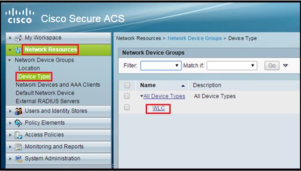
Go to Network Resources > Network Device Groups > Device Type > Create

DVAACS8

Add WLC as AAA client in ACS sever:

Go to Network Resources > Network Devices and AAA Clients. Put the WLC IP and shared secret (it must be same as in WLC)

DVAACS9

DVAACS10

  1. Configure User and Identity Store

Create Identity Group, Users and then assign users to Identity Groups:

In this post we will create three types of users (Production, Admin and Sales Users)

For Identity Groups:

Go to Users and Identity Stores > Identity Groups > Create

For Users:

Go to Users and Identity Stores > Internal Identity Stores > Users > Create

DVAACS11

Create Identity Store Sequence:

As we don’t need it in this post (only internal user option will also work)

Go to Users and Identity Stores > Identity Stores Sequences > Create

DVAACS12

  1. Define policy elements.

Custom Profile

Create a Custom SSID Profile or create an END STATION filter (we will use only one method from this and that will be CUSTOM SSID)

Go to Policy Elements > Custom> Create

Enter the Name (MySSID), choose Dictionary as RADIUS-IETF and Attribute as Called-Station-ID.

DVAACS13

End Station Filter:

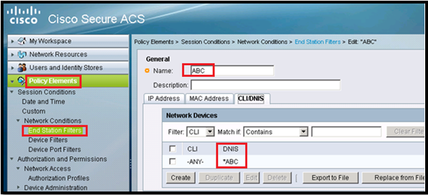
Go to Policy Elements> Network Conditions>End Station Filter>Create

*** We will not use this in this post

DVAACS14

DVAACS15

Create Authorization Profiles:

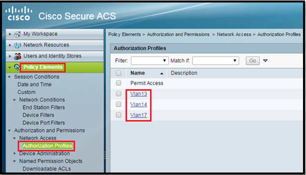
Go to Policy Elements > Authorization and Permissions > Network Access > Authorization Profiles > Create.

IN this post we are using vlan 13, 14 and 17 so we need three Auth Profiles.

Two ways to do: Either under Common Tasks or under RADIUS Attributes:

Both ways are shown here.

DVAACS16

DVAACS17

So in end auth profile will look like this:

DVAACS18

  1. Access Policies

We are using Radius Authentication we have to use Default Network Access.

DVAACS19

Select which EAP method we would like the wireless Clients to Authenticate. In this post we will use EAP-FAST or PEAP.

DVAACS20

Select Identity under Default Network Access as “MyLab” which we created earlier.

DVAACS21

Configure Authorization Rules:

Go to Access Policies > Access Services > Default Network Access > Authorization.

We can customize under what conditions we will allow user access to the network and what authorization profile (attributes) we will pass once authenticated. In this post, we selected Location, SSID, Device Type, and Identity Group.

DVAACS22

Verification

Production User must go in vlan 13.

DVAACS23

Sales User must go in vlan 17.

DVAACS24

Admin User must go in vlan 14.

DVAACS25Logs from ACS:

DVAACS26

Thats all 🙂


Configuration Client Link

In this post we wills learn about Client Link (Beam forming).

As we all know that 802.11n provides remarkable performance improvements in the areas of throughput, link reliability, and predictability. The transition to 802.11n provides significant benefits, but most organizations will take a phased approach to migration.

In the coming days/month/Year, many installations can be expected to support a mix of older 802.11a/g clients and newer 802.11n clients. The reasons that older clients will continue to operate for some time is that it takes few years for a full refresh cycle of enterprise laptops. And certain industries such as manufacturing and healthcare can take even longer to replace their devices.

In mixed environments, older 802.11a/g clients delay communications for 802.11n clients and reduce system performance. That’s y Cisco has developed a new technology that allows businesses to deliver the performance benefits of 802.11n to 802.11a/g devices, thereby increasing their useful life.

Client-Link is a spatial-filtering mechanism used at a transmitter to improve the received signal power or signal-to-noise (SNR) ratio at an intended receiver (client). Cisco Client-Link ensures our mixed 802.11a/g and 802.11n devices operate at the best possible data rates on our wireless networks.

Cisco Aironet 1140, 1250, 1260, 1600, 2600, 2700, 3500 and 3600 series access points support Client-Link.

To know more:  The New Generation of Cisco Aironet Access Points

ClientLink2

Client-Link uses multiple transmit antennas to focus transmissions in the direction of an 802.11a or 802.11g client, which increases the downlink SNR and the data rate to the client, reduces coverage holes, and enhances overall system performance. Client-Link works with all existing 802.11a and 802.11g clients.

Remembering Points:

  1. Client-Link starts only when the signal from the client falls below these thresholds:
    • 11a clients—RSSI of –60 dBm or weaker
    • 11g clients—RSSI of –50 dBm or weaker
  2. 11b clients do not support Client-Link.
  3. The access point actively maintains Client-Link data for up to 15 clients per radio.
  4. Client-Link is supported only for legacy orthogonal frequency-division multiplexing (OFDM) data rates (6, 9, 12, 18, 24, 36, 48, and 54 Mbps).
  5. Client-Link is not supported for complementary code keying (CCK) data rates (1, 2, 5.5, and 11 Mbps).
  6. Only access points that support 802.11n can use Client-Link.
  7. Two or more antennas must be enabled for transmission.
  8. OFDM data rates must be enabled.
  9. Client-Link must be enabled.

Configure Client-Link

Via GUI:

Login to WLC GUI

Go to Wireless > 802.11a/n or 802.11b/g/n > Network

Select the Client-Link check box to globally enable Client-Link on 802.11a or 802.11g network.

Click Apply to commit changes.

The default value is disabled.

See the screenshot:

ClientLink1

To override the global configuration and enable or disable Client-Link for a specific AP as follows (My AP doesn’t support this so cant paste the screenshot):

Choose Wireless > Access Points > Radios > 802.11a/n or 802.11b/g/n

Under the 11n Parameters section, select the Client-Link check box to enable Client-Link for this AP.

Via CLI:

Globally enable or disable ClientLink on your 802.11a or 802.11g network by entering this command:

config {802.11a | 802.11b} beamforming global {enable | disable}

Override the global configuration and enable or disable ClientLink for a specific access point by entering this command:

config {802.11a | 802.11b} beamforming ap Cisco_AP {enable | disable}

Verification:

(WLAN1) >show 802.11a
 802.11a Network.................................. Enabled
 .
 .
 .
 Beacon Interval.................................. 100
 CF Pollable mandatory............................ Disabled
 CF Poll Request mandatory........................ Disabled
 CFP Period....................................... 4
 CFP Maximum Duration............................. 60
 Default Channel.................................. 36
 Default Tx Power Level........................... 1
 DTPC  Status..................................... Enabled
 Fragmentation Threshold.......................... 2346
 TI Threshold..................................... -50
 Legacy Tx Beamforming setting.................... Enabled
 Traffic Stream Metrics Status.................... Disabled
 Expedited BW Request Status...................... Disabled
 World Mode....................................... Enabled
 EDCA profile type................................ default-wmm

Configure Coverage Hole Detection

In this post we will learn about CHD @RRM

Coverage holes are areas where clients can’t receive a signal from the wireless network. If clients on an AP are detected at low received signal strength indicator levels, Cisco lightweight APs send a coverage hole alarm to the cisco WCS/NCS or PI.

The RRM coverage hole detection algorithm can detect areas of radio coverage in a wireless LAN that are below the level needed for robust radio performance. This feature can alert us to the need for an additional (or relocation) lightweight access point.

If clients on a lightweight access point are detected at threshold levels lower than those specified in the RRM configuration, the access point sends a “coverage hole” alert to the controller. The alert indicates the existence of an area where clients are continually experiencing poor signal coverage, without having a viable access point to which to roam.

The controller uses the quality of client signal levels reported by the APs to determine if the power level of that AP needs to be increased. Coverage hole detection is controller independent, so the RF group leader is not involved in those calculations. The controller knows how many clients are associated with a particular AP and what the signal-to-noise ratio (SNR) values are for each client.

If a client SNR drops below the configured threshold value on the controller, the AP increases its power level to try to compensate for the client. The SNR threshold is based on the transmit power of the AP and the coverage profile settings on the controller.

The controller uses the following equation for detecting a coverage hole:

Client SNR Cutoff Value (ldB|) = [AP Transmit Power (dBm) – Constant (17 dBm) -Coverage Profile (dB)]

Depending on the number of clients that are at or below this value for longer than 60 seconds, coverage hole correction might be triggered, and the AP could increase its power level to try to remove the SNR violation.

If the AP is already at power level 1, it cannot increase the power any further, and clients at the edge of the cell coverage suffer a performance hit or disassociate altogether if the signal gets weak enough.

Aside from a real coverage hole, a client with a poor roaming logic might not roam to another AP as expected and be “sticky.” A sticky client can remain associated with an AP until the SNR is very low and triggers a false coverage hole detection.

The coverage hole algorithm also allows the network to heal itself if an AP fails. When a neighbor AP is lost, it increases the power of nearby APs as needed to compensate. Again, the increase in power for an AP is a gradual process, increasing the power one level at a time.

Configure Coverage Hole Detection

Login to WLC GUI, go to Wireless > 802.11a/n or 802.11b/g/n > RRM > Coverage

CHD1

Enable Coverage Hole Detection check box to enable coverage hole detection, or unselect it to disable this feature.

Data/Voice RSSI text box, enter the minimum receive signal strength indication (RSSI) (It must be between -60 to -90 dBm and can be different for voice and data) value for data/voice packets received by the access point. The value that we enter is used to identify coverage holes within our network.

Min Failed Client Count per AP text box, the minimum number of clients on an access point with an RSSI value at or below the data or voice RSSI threshold. The range can be from 1 to 75, and default value is 3.

Coverage Exception Level per AP text box, the percentage of clients on an access point that are experiencing a low signal level but cannot roam to another access point. The range is 0 to 100%, and default value is 25%.

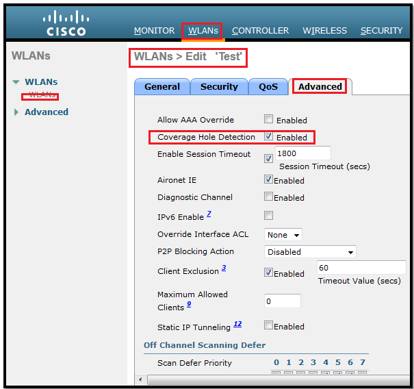
Note: Coverage hole detection is no longer a global setting and can be enabled or disabled on a per-WLAN basis: Coverage hole detection is enabled by default on the WLAN. One of the reasons we might want to disable this is because if we know a device is going to roam, it is advised that we enable the wireless on the device so that it can assist in finding coverage holes. Conversely, if several devices are stationary and have wireless as a backup, it would be advisable to disable this because we know the devices are not going to move and will not be able to provide intelligent information to help the coverage hole detection algorithm with its calculations.

Enable/Disable Coverage Hole Detection per WLAN basis: WLC software release 5.2 or later, we can disable coverage hole detection on a per-WLAN basis

Coverage hole detection is enabled by default on the WLAN.

CHD2

Configure Transmit Power Control

This is one of the features of RRM on WLC and in this post we will see and learn the option under TPC.

This algorithm is responsible for reducing the power level on the APs to reduce excessive cell overlap and co-channel interference. TPC uses the RSSI calculations for the neighbor APs, and it determines effective changes only if there are more than three neighbor APs.

The TPC algorithm runs every 10 minutes (600Secs). The RF group leader runs TPC on a per-radio, per-AP basis. Therefore, a power adjustment on 802.11b/g has no bearing on the 802.11a power level settings for the same AP.

The minimum requirement for TPC is that a single AP needs to be heard by at least three other APs at -70 dBm or greater. Therefore, we must have at least four APs total. The logic behind the lowering of the power levels is that the third loudest neighbor is heard at -70 dBm or lower after the change.

The final purpose of the algorithm is to make sure that the third-loudest neighbor AP is heard at a signal level lower than the configured threshold (by default its –70 dBm).

***Note: The TPC algorithm is only responsible for turning power levels down.

TCP goes through these stages which decide if a transmit power change is necessary:

  1. Find out if there is a third neighbor, and if that third neighbor is above the transmit power control threshold (-70dBm).
  2. Determine the transmit power using this equation:

Tx_Max for given AP + (Tx power control thresh – RSSI of 3rd highest neighbor above the threshold).

  1. Compare the calculation from step two with the current Tx power level and verify if it exceeds the TPC hysteresis.
  • If Tx power needs to be turned down: TPC hysteresis of at least 6dBm must be met. OR
  • If Tx power needs to be increased: TPC hysteresis of 3dBm must be met.

***Note: When a brand new APs boot up for the first time, it transmit at their maximum power level (its 1). When AP is power cycled, it uses their previous power settings.

***Note: It is important to remember that decreases in AP radio power levels are gradual, whereas increases can take place immediately. Therefore, if we change the RRM configuration settings, do not expect to start seeing the APs changing channels and adjusting their power as soon as we click Apply.

Now we will see the configuration steps@TPC

Via GUI:

Go to Wireless -> 802.11a/n or 802.11b/g/n -> RRM ->TPC

On this screen we have these options:

Power Level Assignment Method: There are 3 ways to configure TPC algorithm:

  • Automatic: This is the default configuration and the TPC algorithm runs every ten minutes (600 seconds).
  • On Demand: The algorithm can be manually triggered if we click the Invoke Channel Update Now
  • Fixed

Min/Max Power: Maximum and minimum power level assignment and we can choose between -10 to 30dBm.

Power Threshold: Default value for this parameter is –70 dBm but can be changed when access points are transmitting at higher (or lower) than desired power levels.

Power Neighbor Count: The minimum number of neighbors an AP must have for the TPC algorithm to run.

Power Assignment Leader: This field displays the IP address of the WLC that is currently the RF Group Leader. Because RF Grouping is performed per-AP, per-radio, this value can be different for the 802.11a & 802.11b/g networks.

Last Power Level Assignment: The TPC algorithm runs every 600 seconds (10 minutes). This field only indicates the time (in seconds) since the algorithm last.

Verification:

(WLAN1) >show advanced 802.11a txpower
 Automatic Transmit Power Assignment
 Transmit Power Assignment Mode................. OFF
 Transmit Power Update Interval................. 600 seconds
 Transmit Power Threshold....................... -70 dBm
 Transmit Power Neighbor Count.................. 3 APs
 Min Transmit Power............................. -10 dBm
 Max Transmit Power............................. 30 dBm
 Transmit Power Update Contribution............. SNI..
 Transmit Power Assignment Leader............... WLAN1 (10.35.80.1)
 Last Run....................................... 98 seconds ago

Configure Dynamic Channel Assignment

In this post we will learn about DCA and it’s a really cool feature of RRM.

DCA is managed by RF Group Leader (How to define RF leader, we saw in one of my last post)

DCA used to determine the optimal AP channel based on these parameters.

Load: Percentage of time spent transmitting 802.11 frames

Noise: Measurement of non-802.11 signals on every serviced channel

Interference: Percentage of radio time used by neighbor 802.11 transmissions

Signal strength: Received signal strength indication (RSSI) measurement of the received neighbor messages

These values are then used by the Group Leader to determine if another channel schema will result in at least a bettering of the worst performing AP by 5dB (SNR) or in other words: Based on these metrics, if the worst performing AP will benefit by at least 5 dB or more, a channel change will take place. The decision to change the channel of an AP is also weighted to prevent a mass change within the RF group. We would not want to have a single AP change channel and have that change result in 20 other APs having to change their channel. The controller also takes into account how heavily an AP is used. A less utilized AP is more likely to have a channel change instead of a heavily used neighbor (isn’t it an interesting feature?). This helps mitigate client disassociations during a DCA event because a radio channel change disconnects all associated clients.
***Note: When an AP first boots up out the box, it transmits on channel 1 on the 802.11b/g radio and channel 36 for the 802.11a radio. The channels change according to any DCA adjustments if necessary. If a reboot occurs, the APs remain on the same channel they were using before the reboot until a DCA event occurs. If an AP is on channel 152 and reboots, it will continue to use channel 152 when it comes back up.

***Note: Radios using 40-MHz channels in the 2.4-GHz band or or 80MHz channels are not supported by DCA.

The RRM startup mode is invoked in the following conditions:

  • In a single-controller environment, the RRM startup mode is invoked after the controller is rebooted.
  • In a multiple-controller environment, the RRM startup mode is invoked after an RF Group leader is elected.

Configure DCA:

***We must disable 802.11a and b radio before changing the config. for DCA and then enable it again. Simplest way to enable/disable the radio is via CLI:

(WLAN1) >config 802.11a disable network
(WLAN1) >config 802.11a enable network

Go to Wireless > 802.11a/n or 802.11b/g/n > RRM > DCA

DCA1

DCA2

There is three type of Channel Assignment Method.

Channel Assignment Mode:

  • Automatic: This mode will cause the controller to periodically evaluate and, if necessary, update the channel assignment for all joined access points.
  • Freeze: It will Causes the controller to evaluate and update the channel assignment for all joined access points, but only when we click Invoke Channel Update Once.
  • OFF: Turns off DCA and sets all access point radios to the first channel of the band.

Avoid Foreign AP Interference:  It detect foreign AP and take into consideration while changing the channel.

Avoid Cisco AP Load: When its enabled then the AP load is taken into account before result in which AP will change the channel (least loaded AP will change the channel first.

Avoid Non-802.11a (802.11b) Noise: It cause the controller’s RRM algorithms to consider noise (non-802.11 traffic) in the channel when assigning channels to lightweight access points.

Avoid Persistent Non-Wi-Fi Interference:  Its enable the controller to ignore or avoid from persistent non-Wi-Fi interference.

Channel Assignment Leader: The IP address of the RF group leader, which is fully responsible for channel assignment.

Last Auto Channel Assignment: The last time RRM evaluated the current channel assignments.

DCA Channel Sensitivity: We have 3 levels (Low, Medium and High)

Channel Width:  depends on the 802.11a or b radios:  5GHz select 40MHz. In 2.4 GHz it will be 20MHz.

Avoid check for non-DFS channel: Enabled then the controller avoid checks for non-DFS channels. (Apply only for outdoor APs)

DCA Channel List: This option shows the selected channel on this radio.


Dont forget to enable both radios after changing the parameter in this section by using these commands 🙂

RRM (Radio Resource Management) Overview

The RRM feature is also known as Auto-RF or act as a built –in RF engineer in controller, uses the RF information gathered by the APs to make decisions on whether channel assignment or power levels need to be adjusted.

In other words: It uses the RF information gathered by the APs to make decisions on whether channel assignment or power levels need to be adjusted. Just because the RF environment has changed does not necessarily mean that the controller will change.

Before covering the intricacies of the RRM algorithm and RF grouping, following is a high-level overview of the basic workflow involved:

Step 1: The controllers and their APs use the configured RF group name to determine if other APs they hear are part of their RF group.

Step 2: The APs use neighbor messages (sent every 60 seconds) that are authenticated by other APs that hear them. The neighbor messages include information about the AP, the controller, and the configured RF group name.

Step 3: The APs that hear the neighbor message of another AP authenticate that message using the RF group name and pass it to their respective controller.

Step 4: The controllers use this information to determine what other controllers should be in their RF group, and then form logical groups to share the RF information from their respective APs, and elect an RF group leader.

Step 5: The RF group leader runs the RRM algorithm against the RF information from all the APs in the RF group. Depending on the outcome, a power level or channel change for an AP or group of APs might take place.

To know more details about RRM, check this previous post:

https://rscciew.wordpress.com/2013/12/04/radio-resource-management/

Also don’t forget to see these YouTube video by Jerome Henry:

  1. http://www.youtube.com/watch?v=gwCxVwmHnRw – describes RRM principles
  2. http://www.youtube.com/watch?v=XhmnXeeLQBc – goes deeper into RRM and provides useful information if you are to take a Cisco exam on Wireless related topics! 🙂
  3. http://www.youtube.com/watch?v=3EnvhxjzEWU – details how RRM controls the AP channel assignment with DCA (Dynamic Channel Assignment).
  4. http://www.youtube.com/watch?v=32YWzuXTg5M – explains how RRM dynamically reduces AP power with TPC (Transmit Power Control)
  5. http://www.youtube.com/watch?v=yot63RsKOCg – explains how the Radio Coverage Detection Algorithm works.

RRM feature enables controllers to continually monitor their associated LAP for the following information:

  • Traffic load: The total bandwidth used for transmitting and receiving traffic. It enables wireless LAN managers to track and plan network growth ahead of client demand.
  • Interference: The amount of traffic coming from other 802.11 sources.
  • Noise: The amount of non-802.11 traffic that is interfering with the currently assigned channel.
  • Coverage: The received signal strength (RSSI) and signal-to-noise ratio (SNR) for all connected clients.
  • Other: The number of nearby access points.

RRM performs these functions:

  • Radio resource monitoring
  • Transmit power control
  • Dynamic channel assignment
  • Coverage hole detection and correction

In this post we will see the configuration guide of RRM on WLC.

Configure an RF Group Name

Via GUI:

First step to configure RRM is to ensure WLC has the RF Group Name configured. This can be done through the controller web interface. Go to Controller > General and then type a RF Group Name value.

RRM1

Via CLI:

Create an RF group by entering the config network rf-network-name name command:

(WLAN1) >config network rf-network-name mywlc

Configuring the RF Group Mode:

Via GUI

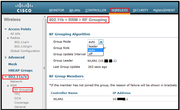
Go to Wireless > 802.11a/n or 802.11b/g/n > RRM > RF Grouping

RRM2

Via CLI:

config advanced {802.11a | 802.11b} group-mode {auto | leader| off | restart}

(WLAN1) >config advanced 802.11a group-mode ?
 auto           Sets the 802.11a RF group selection to automatic update mode.
 leader         Sets the 802.11a RF group selection to static mode, and sets this controller as the group leader.
 off            Sets the 802.11a RF group selection off.
 restart        Restarts the 802.11a RF group selection.
(WLAN1) >config advanced 802.11a group-mode auto

On this screen we can see the details of RF group

Group Mode: Auto (It can be static or we can disable it)

Group Role: Auto Leader or Static Leader

Group Update Interval: The group update interval value indicates how often the RF Grouping algorithm is run and it cannot be modified.

Group Leader: This field displays the IP Address of the WLC that is currently the RF Group Leader.

Last Group Update: The RF Grouping algorithm runs every 600 seconds (10 minutes). This field indicates the time (in seconds) since the algorithm last ran.

RRM3

*** A configured static leader cannot become a member of another controller until its mode is set to “auto”.

No we will change the Group mode on Controller”WLAN1” as leader.

RRM4

Add a controller as member:

RRM5

Via CLI:

Add a controller as a static member of the RF group (if the mode is set to “leader”) by entering this command:

config advanced {802.11a | 802.11b} group-mode {auto | leader| off | restart}

(WLAN1) >config advanced 802.11agroup-mode leader

config advanced 802.11a | 802. group-member add controller_name controller_ip_address

(WLAN1) >config advanced 802.11a | 802. group-member add WLAN2 10.35.80.3

To see RF grouping status

(WLAN1) >show advanced 802.11a group
 Radio RF Grouping
 802.11a Group Mode............................. STATIC
 802.11a Group Update Interval.................. 600 seconds
 802.11a Group Leader........................... WLAN1 (10.35.80.1)
 802.11a Group Member......................... WLAN1 (10.35.80.1)
 802.11a Group Member......................... WLAN2 (10.35.80.3)
 802.11a Last Run............................... 17 seconds ago
 * indicates member has not joined the group.
 (WLAN1) >

*** Same procedure for 802.11b network

***Info:

There are few things we must take care before forcing a WLC to be a RF leader:

  1. All WLC members must have the same mobility and RF group name.
  2. All WLCs AP must be in the range of each other.

In next post we will learn TPC, DCA and CHD.