Autonomous AP with Local RADIUS server – EAP FAST

In this post we will see, how to configure a standalone AP to act as AUTHENTCATOR SERVER (RADIUS).

Standalone AP can be configured as local RADIUS server to provide the AAA service.

This kind of solution can be used in small scale deployment or which can not afford to buy ACS or ISE and It can also provide as a backup RADIUS server in case of primary fails.

Normally Autonomous AP can use three types authentication:

*** EAP-TLS is not supported on Autonomous AP.

First we will configure for EAP-FAST 🙂

I will create one SSID”data1” and map to specific VLAN”101”.

Remembering points:

  1. The local RADIUS server uses UDP ports 1812 and 1813.
  2. Keep the config as simple as possible.
  3. In this type of scenario, AP is using as Authenticator and Authenticator server (Both).
  4. AP can authenticate max 50 client’s devices.
  5. AP performs up to 5 authentications per second.
  6. When AP acts as Local authenticator, performance may decrease for associated clients.

Steps to Configure:

  1. Configure the local AP as NAS (Network Access Server).
  2. Create user groups
  3. Create users to authorize to authenticate.
  4. Enter the local authenticator as radius server.

We can configure by two ways: GUI and CLI

Via CLI:

Switch config for AP connection:

int fa 0/15
  switchport mode trunk
  switchport trunk encapsulation dot1q
  switchport trunk allowed vlan 100, 101

Step1: Configure the SSID and map to a VLAN

Config t
 Dot11 ssid data1 
 Vlan 101
 Authentication open eap local_eap
 Authentication network-eap local_eap
 Authentication key-management wpa version 2
 Guest-mode
 end

Step2: Configure the radio and Ethernet interface

Config t
 Interface dot11Radio0
 ssid data1
 exit
Interface dot11Radio0.100
 encapsulation dot1Q 100
Interface dot11Radio0.101
 encapsulation dot1Q 101
 bridge-group 101
 exit
int fa 0.100
 encapsulation dot1Q 1080
Interface fa0.101
 encapsulation dot1Q 101
 bridge-group 101
 exit

Step3: Assign encryption to SSIDs with VLAN

Int dot11Radio0
 Encryption vlan 101 mode  ciphers aes-ccm

Step4: Configure AP for management

Int BVI1
 Ip address 10.35.100.15 255.255.255.0
 !
 Ip default-gateway 10.35.100.254

Step5: Define a AAA group, AAA login method and configure RADIUS server with its own IP address

aaa new-model
 aaa group server radius radius_fast
 server 10.35.100.15 auth-port 1812 acct-port 1813
 aaa authentication login local_eap group radius_fast

Step6: Configure local AP as authenticator

radius-server host 10.35.100.15 auth-port 1812 acct-port 1813 key fast12345 

Step7: Configure local users to authenticate as NAS entries.

Radius server local
 Nas 10.35.100.15 key fast12345
 User Sandeep password test12345
 User sandeep1 password rscciew12345

Step8: Configure EAP-FAST Settings (authority ID, Info, server key…Etc.).

Authority ID

All EAP-FAST authenticators are identified by an authority identity (AID). The local authenticator sends its AID to an authenticating client, and the client checks its database for a matching AID. If the client does not recognize the AID, it requests a new PAC.

AP002(config)#radius-server local
AP002(config-radsrv)#eapfast authority id ?
 Hex-data  32 hexadecimal digits
AP002(config-radsrv)#eapfast authority id 98765432198765432198765432198765

Authority Info:

AP002(config-radsrv)#eapfast authority info ?
 LINE ASCII string (32 char)
AP002(config-radsrv)#eapfast authority info cisco

Server Key

The local authenticator uses server keys to encrypt PACs that it generates and to decrypt PACs when authenticating clients. The server maintains two keys, primary key and secondary key, and uses the primary key to encrypt PACs. By default, the server uses a default value as the primary key but does not use a secondary key unless we configure one.
When the local authenticator receives a client PAC, it attempts to decrypt the PAC with the primary key. If decryption fails with the primary, the authenticator attempts to decrypt the PAC with the secondary key if one is configured. If decryption fails, the authenticator rejects the PAC as invalid.

AP002(config-radsrv)#eapfast server-key ?
 primary primary key
 secondary secondary key
AP002(config-radsrv)#eapfast server-key primary ?
 0 Specifies an UNENCRYPTED password will follow
 7 Specifies an HIDDEN password will follow
 Hex-data 32 hexadecimal digits
 auto-generate auto generate the key
AP002(config-radsrv)#eapfast server-key primary auto-generate

AP002(config-radsrv)#eapfast server-key secondary ?
 0 Specifies an UNENCRYPTED password will follow
 7 Specifies an HIDDEN password will follow
 Hex-data 32 hexadecimal digits
AP002(config-radsrv)#eapfast server-key secondary 98765432198765432198765432198765
AP002(config-radsrv)#

PAC Generation for specific Username

The local authenticator automatically generates PACs for EAP-FAST clients that request them. However, we might need to generate a PAC manually for some client devices. When we enter the command, the local authenticator generates a PAC file and writes it to the network location that we specify. The user imports the PAC file into the client profile.
Use this command to generate a PAC manually:

AP002#radius local-server pac-generate ?
 WORD username, for which PAC to be issued
AP002#radius local-server pac-generate sandeep1 ?
 WORD filename to save generated PAC(ex: tftp://172.1.1.1/test/user.pac)
AP002#radius local-server pac-generate sandeep1 tftp://10.35.100.100/sandeep1.pac password rscciew12345 expiry 10
 Generating PAC for the user: sandeep1
!!
AP002#

Step9: Verification

AP002#sh dot11 associations
 802.11 Client Stations on Dot11Radio0:
 SSID [data1] :
 MAC Address    IP address      Device        Name            Parent         State
 bd7b.a1d1.c289 10.35.101.152    ccx-client    AP002           self           EAP-Assoc
 AP002#sh dot11 associations  ac7b.a1d1.c289
 Address           : bd7b.a1d1.c289     Name             : AP002
 IP Address        : 10.35.101.152       Interface        : Dot11Radio 0
 Device            : ccx-client         Software Version : NONE
 CCX Version       : 4                  Client MFP       : Off
 State             : EAP-Assoc          Parent           : self
 SSID              : data1
 VLAN              : 81
 Hops to Infra     : 1                  Association Id   : 1
 Clients Associated: 0                  Repeaters associated: 0
 Tunnel Address    : 0.0.0.0
 Key Mgmt type     : WPAv2              Encryption       : AES-CCMP
 Current Rate      : 54.0               Capability       : WMM ShortHdr ShortSlot
 Supported Rates   : 1.0 2.0 5.5 11.0 6.0 9.0 12.0 18.0 24.0 36.0 48.0 54.0
 Voice Rates       : disabled           Bandwidth        : 20 MHz
 Signal Strength   : -33  dBm           Connected for    : 31 seconds
 Signal to Noise   : 59  dB            Activity Timeout : 50 seconds
 Power-save        : On                 Last Activity    : 0 seconds ago
 Apsd DE AC(s)     : BK BE VI VO
 Packets Input     : 640                Packets Output   : 353
 Bytes Input       : 61156              Bytes Output     : 35666
 Duplicates Rcvd   : 0                  Data Retries     : 27
 Decrypt Failed    : 0                  RTS Retries      : 73
 MIC Failed        : 0                  MIC Missing      : 0
 Packets Redirected: 0                  Redirect Filtered: 0
 Session timeout   : 0 seconds
 Reauthenticate in : never
 AP002#

 Screenshot:


leap_autonomous

Thats all for today 🙂

———x———————————————-

Step8 can also be configured in this way :

radius-server local
 eapfast authority id 01234567890123456789012345678901
 eapfast authority info cisco
 eapfast server-key primary 12345678901234567890123456789012
 eapfast server-key secondary 12345678901234567890123456789012
 nas 10.35.100.15 key  fast12345
 user Sandeep password test12345
 user sandeep1 password rscciew12345

DHCP with the WLC

To get a brief overview about DHCP process in Wired Infrastructure, please see my previous post: DHCP Basics
In this post we will see the different DHCP operation on Cisco Wireless LAN Controller.
As we all know that we can use External or internal DHCP server for wireless clients via Cisco WLC.

Topology Diagram:

DHCPWirelessTopology

So first we will go through the configuration and functionality of external DHCP server for a WLAN.

External DHCP Server:

WLC can support two modes in case of External DHCP server.

  1. DHCP proxy
  2. DHCP Bridging

DHCP Proxy Mode:

To use the controller as a DHCP proxy, the DHCP proxy feature must be enabled on the controller. By default, this feature is enabled.

DHCP server must be configured on each WLC interface that requires DHCP services. A DHCP server can be configured on the management interface, AP-manager interface, and on dynamic interfaces.

Configuration

To enable DHCP proxy and DHCP server configuration WLC interface:

Via GUI:

Enable DHCP Proxy

DHCPProxy

Enter DHCP IP for WLC Interface: (It just an example)

DHCP on Interface

Via CLI:

Enable DHCP Proxy

(WLC1) >config dhcp proxy enable
 (WLC1) >show dhcp proxy
 DHCP Proxy Behavior: enabled

Configure DHCP server IP on WLC Interface:

Example:

(WLC1) >config interface dhcp dynamic-interface <interface-name> primary <primary-server> secondary <secondary-server>
 (WLC1) >config interface dhcp dynamic-interface guest primary 192.168.10.1 secondary 0.0.0.0
  • The DHCP proxy mode serves as a DHCP helper function to achieve better security and control over DHCP transaction between the DHCP server and the wireless clients.
  • In this mode Controller virtual IP address (1.1.1.1 or depends on …what we have) as source IP address for all DHCP process for client means we will not see the exact DHCP server IP address in our packet capture.
  • When multiple offers are coming from external DHCP servers, the DHCP proxy normally selects the first one that comes in and sets the IP address of the server in the client data structure. As a result, all following transactions go through the same DHCP server until a transaction fails after retries. At this point, the proxy selects a different DHCP server for the client.
  • DHCP proxy is enabled by default. All controllers that will communicate must have the same DHCP proxy setting.
  • In this DHCP proxy mode, it is not only directing DHCP packets to the DHCP server, it is actually building new DHCP packets to forward to the DHCP server. All DHCP options which are present in the client’s DHCP packets are copied in the controller’s DHCP packets.

Packet flow:

  1. Client boots up and send DHCP Discover on all subnet broadcast.
  2. WLC unicast this packet to DHCP server(as configured on WLC interface)
  3. DHCP server send DHCP offer to WLC.
  4. WLC unicast DHCP offer to Client with source address as WLC virtual IP address.
  5. Client send DHCP request to WLC on Virtual address because Client think that this virtual IP is DHCP server address
  6. WLC unicast DHCP request to DHCP server which returned the first offer to the client.
  7. DHCP server send ACK to WLC
  8. WLC unicast ACK from virtual IP to the client.

Let see the packet capture from Client side:

DHCP Discover Packet:

ExtDHCPDiscover

1.1.1.1 is the WLC Virtual Interface IP address
10.xx.xx.13 is the Client IP address.

DHCP Offer:

ExtDHCPOffer

DHCP Request:

ExtDHCPRequest

DHCP ACK:

ExtDHCPACK


DHCP Bridge Mode

DHCP bridging mode provides an option to make controller’s role in DHCP transaction entirely transparent to the wireless clients.

Configuration:

To enable the DHCP bridging functionality on the controller, we must disable the DHCP proxy feature on the controller.

Via GUI:

DisbaleProxy

Via CLI:

(WLC1) >config dhcp proxy disable
 (WLC1) >show dhcp proxy
 DHCP Proxy Behaviour: disabled

Packet Flow:

  1. Client send DHCP Discover on all subnet broadcast which is bridged by controller
  2. DHCP server send DHCP offer to Client
  3. Client send DHCP request to all subnet
  4. DHCP server send ACK to client in unicast packet

Let see the packet capture from Client Side:

DHCP Discover:

BridgeDHCPDiscover

DHCP Offer:

BridgeDHCPOffer

10.xx.xx.254 is the Router Gateway IP address
10.xx.xx.13 is the client IP address
10.xx.xx.1 is the DHCP server IP address

DHCP Request:

BridgeDHCPRequest

DHCP ACK:

BridgeDHCPAck

Internal DHCP Server:

Internal DHCP is used for small office where external DHCP server is not possible to use.

Cisco recommend to use internal DHCP with less than 10 AP in network, if we have more AP then 10 then better to use external DCHP.

Internal DHCP provide IP to WLAN clients, directly connected APs.

Internal DHCP Server Configuration:

We must enable DHCP proxy on the controller to allow the internal DHCP server to function.

Via GUI:

InternalDHCPProxy

Via CLI:

Enable DHCP Proxy

(WLC1) >config dhcp proxy enable
 (WLC1) >show dhcp proxy
 DHCP Proxy Behavior: enabled

*** For internal DHCP we must create a DHCP scope for specific interface and put the WLC management IP in interface primary DHCP server configuration box or Point DHCP override to the management interface IP address of our controller under WLAN > edit

How to Create DHCP Scope: Login to WLC GUI then goes to Controller >Internal DHCP Server >DHCP Scope > New

DHCP Scope

Assign DHCP Server :

On Dynamic Interface:

See the 2nd Pic of the post.

DHCP override to the management interface IP per WLAN.

DHCP Override

Packet Flow:

  1. Client send DHCP discover on all subnet as broadcast
  2. WLC forward the DHCP discover via DHCP proxy to internal DHCP server ip address(Management interface IP of WLC)
  3. Internal DHCP server send DHCP offer to WLC proxy agent.
  4. WLC send unicast DHCP offer to client with source address of WLC management Interface IP.
  5. Client send DHCP request to WLC on management interface IP.
  6. WLC send unicast DHCP request to internal server via DHCP proxy
  7. Internal DHCP server sends DHCP ACK to DHCP proxy.
  8. WLC send unicast DHCP ACK to client

Just small Info in short to remember: Many guys like me have confusion between these two words:

A DHCP proxy server has a fully-functional DHCP client and DHCP server implementation in it. The client part requests addresses from another DHCP server and stores them in an internal address pool while the server part listens to DHCP requests from clients and uses this internal pool to lease the addresses.(like: Internal DHCP server)

A DHCP relay agent listens to the broadcast DHCP requests from clients and forward them to another DHCP server (usually per unicast).

*** In both DHCP relay and DHCP proxy cases the clients will never see the real DHCP server but rather will consider the intermediate element as their DHCP server.

Let’s see the packet capture from Client side:

DHCP Discover:

InternalDHCPDiscover

DHCP Offer:

InternalDHCPOffer

DHCP Request:

InternalDHCPRequest

 DHCP ACK:

InternalDHCPAck

10.xx.xx.26 is the client IP address.
10.xx.xx.254 is the Router Gateway IP address.


DHCP Basics

In this post we will learn about DHCP protocol messages and its functionality.

DHCP stands for Dynamic Host Configuration Protocol. DHCP provides an automated way to distribute and update IP addresses and other configuration information on a network. A DHCP server provides this information to a DHCP client through the exchange of a series of messages, known as the DHCP conversation or the DHCP transaction. If the DHCP server and DHCP clients are located on different subnets, a DHCP relay agent is used to facilitate the conversation.

Before going to the process through which DHCP achieves its goal, we first have to understand the different messages that are used in the process.

  1. DHCPDISCOVER

It is a DHCP message that marks the beginning of a DHCP interaction between client and server. This message is sent by a client that is connected to a local subnet. It’s a broadcast message that uses 255.255.255.255 as destination IP address while the source IP address is 0.0.0.0

  1. DHCPOFFER

It is DHCP message that is sent in response to DHCPDISCOVER by a DHCP server to DHCP client. This message contains the network configuration settings for the client that sent the DHCPDISCOVER message.

  1. DHCPREQUEST

This DHCP message is sent in response to DHCPOFFER indicating that the client has accepted the network configuration sent in DHCPOFFER message from the server.

  1. DHCPACK

This message is sent by the DHCP server in response to DHCPREQUEST received from the client. This message marks the end of the process that started with DHCPDISCOVER. The DHCPACK message is nothing but an acknowledgement by the DHCP server that authorizes the DHCP client to start using the network configuration it received from the DHCP server earlier.

  1. DHCPNAK

This message is the exact opposite to DHCPACK described above. This message is sent by the DHCP server when it is not able to satisfy the DHCPREQUEST message from the client.

  1. DHCPDECLINE

This message is sent from the DHCP client to the server in case the client finds that the IP address assigned by DHCP server is already in use.

  1. DHCPINFORM

This message is sent from the DHCP client in case the IP address is statically configured on the client and only other network settings or configurations are desired to be dynamically acquired from DHCP server.

  1. DHCPRELEASE

This message is sent by the DHCP client in case it wants to terminate the lease of network address it has to be provided by DHCP server.

DHCPTopology

DHCP for process

Let’s check how DHCP works in wired environment with the help of Wire-Shark Packets:

DHCP_Wireshark

As per the Wire-Shark output, we can see that 4 steps (4 types of packets) are there, called D.O.R.A (Discover, Offer, Request, ACK) process.

Let’s go in to deep….

Step 1: When the client computer boots up or is connected to a network, a DHCPDISCOVER message is sent from the client to the server. As there is no network configuration information on the client so the message is sent with 0.0.0.0 as source address and 255.255.255.255 as destination address. If the DHCP server is on local subnet then it directly receives the message or in case it is on different subnet then a relay agent connected on client’s subnet is used to pass on the request to DHCP server. The transport protocol used for this message is UDP and the port number used is 67. The client enters the initializing stage during this step.

DHCPWiredDiscover

Step2: When the DHCP server receives the DHCPDISCOVER request message then it replies with a DHCPOFFER message. This message contains all the network configuration settings required by the client. This message is sent as a broadcast (255.255.255.255) message for the client to receive it directly or if DHCP server is in different subnet then this message is sent to the relay agent that takes care of whether the message is to be passed as unicast or broadcast. In this case also, UDP protocol is used at the transport layer with destination port as 68. The client enters selecting stage during this step.(In this I have Client on same subnet as DHCP server so it will not send to any the relay agent)

DHCPWiredOffer

Step3: The client forms a DHCPREQUEST message in reply to DHCPOFFER message and sends it to the server indicating it wants to accept the network configuration sent in the DHCPOFFER message. If there were multiple DHCP servers that received DHCPDISCOVER then client could receive multiple DHCPOFFER messages. But, the client replies to only one of the messages by populating the server identification field with the IP address of a particular DHCP server. All the messages from other DHCP servers are implicitly declined. The DHCPREQUEST message will still contain the source address as 0.0.0.0 as the client is still not allowed to use the IP address passed to it through DHCPOFFER message. The client enters requesting stage during this step.

DHCPWiredRequest

Step 4: Once the server receives DHCPREQUEST from the client, it sends the DHCPACK message indicating that now the client is allowed to use the IP address assigned to it. The client enters the bound state during this step.

DHCPWiredACK

DHCP LEASE: (We can see the lease time in DHCP ACK packets, as per above screenshot) The IP address assigned by DHCP server to DHCP client is on a lease. After the lease expires the DHCP server is free to assign the same IP address to any other host or device requesting for the same.

A DHCP-enabled client obtains a lease for an IP address from a DHCP server. Before the lease expires, the DHCP server must renew the lease for the client or the client must obtain a new lease.

In the next post will see the DHCP process in Wireless (or DHCP with the WLC).


Schedule a reboot to Controller via CLI

In this post we will see to schedule reboot to wlc.

Schedule a reboot Time for WLC via CLI. This is really a good option on CLI to reboot WLC at specific time.

Let’s see the configuration guide.

What are the options on WLC CLI to reset:

(WLC1) >reset system ?
 at             Reset the system at a specified time.
 in             Reset the system after a specified delay.
 cancel         Cancel a scheduled reset.
 notify-time    Configures trap generation prior to scheduled resets.
(WLC1) >

RESET SYSTEM AT:

Specify a date and time for the devices to reboot by entering this command: This command allows us to enter a specific date and time to reboot controller.

*** The swap operand in the reset command will result in the swapping of the primary and backup images on both the controller and the access point.

(WLC1) >reset system at 2014-07-11 18:00:00 image no-swap reset-aps save-config
 System reset is scheduled for Jul 11 18:00:00 2014.
 Current local time and date is Jul 11 09:10:19 2014.
 A trap will be generated 10 minutes before each scheduled system reset.
 Use 'reset system cancel' to cancel the reset.
 Configuration will be saved before the system reset.
 (WLC1) >

RESET SYSTEM IN:

Specify the amount of time delay before the devices reboot by entering this command: This command allows us to enter a specific time to reboot controller.

(WLC1) >reset system in 18:00:00 image  no-swap reset-aps save-config
 System reset is scheduled for Jul 12 03:10:59 2014.
 Current local time and date is Jul 11 09:10:59 2014.
 A trap will be generated 10 minutes before each scheduled system reset.
 Use 'reset system cancel' to cancel the reset.
 Configuration will be saved before the system reset.
(WLC1) >

RESET SYSTEM NOTIFY-TIME :

Set up an SNMP trap message that announces the upcoming reset by entering this command: After configuring this command, controller sends the announcement trap the configured number of minutes before the reset.

(WLC1) >reset system notify-time 10
 A trap will be generated 10 minutes before each scheduled system reset.
(WLC1) >

RESET SYSTEM CANCEL:

Cancel the scheduled reboot by entering this command: We scheduled a system reset and need to cancel it then we just need to apply the reset system cancel command.

(WLC1) >reset system cancel
 Scheduled reset cancelled.
(WLC1) >

SHOW RESET:

Use show reset command to display scheduled resets.

(WLC1) >show reset
 System reset is scheduled for Jul 12 03:11:51 2014.
 Current local time and date is Jul 11 09:11:53 2014.
 A trap will be generated 10 minutes before each scheduled system reset.
 Use 'reset system cancel' to cancel the reset.
 Configuration will be saved before the system reset.
(WLC1) >

Reset Cisco WLC to Factory Default

Just a small post regarding WLC reset, it can be done without NCS and it’s very handy.

Via CLI:

Step1: We need to login to WLC with valid username and password then we need to reset the WLC by using “reset system” at the command prompt.

(WLAN1) >reset system
 The system has unsaved changes.
 Would you like to save them now? (y/N) Y
 Configuration Saved!
 System will now restart!

Step2:  At the prompt it will ask whether we need to save changes to the configuration, enter Yes or No, then controller will reboot.

.
.
(WLAN1)
 Enter User Name (or 'Recover-Config' this one-time only to reset configuration to factory defaults)
 User:

Step3: When we are prompted for a username then we must enter recover-config to restore the factory default configuration.

User:  recover-config
Press enter and the controller will reset back to factory default.

Via GUI:

  1. login to WLC GUI with valid username and password.
  2. Go to Command > Reset to Factory Default.
  3. Click Reset.


Resetwlc1

That’s all  🙂

Mobility Test between Controllers

In this post we will test the mobility ping between 2 controllers.

You can check here : How to Configure Mobility on WLC

Controllers in a mobility list communicate with each other by controlling information over a well-known UDP port and exchanging data traffic through an Ethernet-over-IP (EoIP) tunnel. Because UDP and EoIP are not reliable transport mechanisms, there is no guarantee that a mobility control packet or data packet will be delivered to a mobility peer. Mobility packets may be lost in transit due to a firewall filtering the UDP port or EoIP packets or due to routing issues.

We can test the mobility communication environment by performing mobility ping tests. These tests may be used to validate connectivity between members of a mobility group.

Two are two types of ping test:

Mobility ping over UDP: This test runs over mobility UDP port 16666. It tests whether the mobility control packet can be reached over the management interface.

Mobility ping over EoIP: This test runs over EoIP(Port 97). It tests the mobility data traffic over the management interface.

*** Only one mobility ping test per controller can be run at a given time.

These ping tests are not Internet Control Message Protocol (ICMP) based. The term “ping” is used to indicate an echo request and an echo reply message.

Check which WLCs are in mobility list:

(WLC1) >show mobility summary
 Symmetric Mobility Tunneling (current) .......... Enabled
 Symmetric Mobility Tunneling (after reboot) ..... Enabled
 Mobility Protocol Port........................... 16666
 Default Mobility Domain.......................... Test
 Multicast Mode .................................. Disabled
 Mobility Domain ID for 802.11r................... 0x840e
 Mobility Keepalive Interval...................... 10
 Mobility Keepalive Count......................... 3
 Mobility Group Members Configured................ 2
 Mobility Control Message DSCP Value.............. 0
 Controllers configured in the Mobility Group
 MAC Address        IP Address       Group Name                        Multicast IP     Status
 00:21:d8:fa:66:00  192.168.80.1       Test                              0.0.0.0          Up
 00:21:d8:fa:fd:a0  192.168.82.1       Test                              0.0.0.0          Up


To test the mobility UDP control packet communication between two controllers, enter this command: mping mobility_peer_IP_address

(WLC1) >mping 192.168.82.1
 Send count=3, Receive count=3 from 192.168.82.1
(WLC1) >

To test the mobility EoIP data packet communication between two controllers, enter this command: eping mobility_peer_IP_address

(WLC1) >eping 192.168.82.1
 Send count=3, Receive count=3 from 192.168.82.1
(WLC1) >

Layer 3- Inter Controller Roaming

In this post we will see how the Layer 3 Roaming( inter subnet controller) roaming works on Controller.

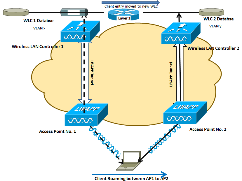
Here is my topology:

L3Inter1

WLC1: 10.99.80.1, AP001 is connected to it
WLC2: 10.99.82.1, AP002 is connected to it.

If the client roams between APs registered to different controllers and the client WLAN on the two controllers is on different subnets, then an inter-subnet roam, or Layer 3 mobility event, takes place. For example, if a client is on WLAN-X on Controller-1 using VLANx and the client roams to WLAN-X on Controller-2, but WLAN-X on controller-2 is using VLANy, then an inter-subnet roam for that client occurs.

Inter-subnet roaming is similar to inter-controller roaming in that the controllers exchange mobility messages on the client roam. However, instead of moving the client database entry to the new controller, the original controller marks the client with an “Anchor” entry in its own client database. The database entry is copied to the new controller client database and marked with a “Foreign” entry in the new controller. The roam remains transparent to the wireless client, and the client maintains its original IP address.

In inter-subnet roaming, WLANs on both anchor and foreign controllers need to have the same network access privileges and no source-based routing or source-based firewalls in place. Otherwise, the clients may have network connectivity issues after the handoff.
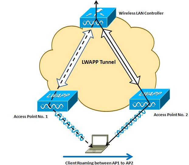
Or

When the client roams between them, the controllers still exchange mobility messages, but they handle the client database entry in a completely different manner. The original controller marks the client entry as Anchor, whereas the new controller marks the client entry as Foreign. The two controllers are now referred to as anchor and foreign, respectively. The client has no knowledge of this and retains its original IP address on the new controller. Traffic flow to and from the client on the network becomes asymmetrical. Traffic from the client is bridged directly to the wired network by the foreign controller. The foreign controller spoofs the IP and MAC address of the client. Traffic from the wired network to the client, however, is received by the original controller and sent to the new controller through an Ethernet over IP (EtherIP) tunnel to the new controller. The new controller then passes that traffic to the client.

If the client roams back to the original controller, the Anchor and Foreign markings are removed and the client database entry is deleted from the foreign controller. If the client should roam to a different foreign controller, the original anchor controller is maintained, and the foreign client entry is transferred to the new foreign controller.

First my client is already connected to AP001.

See the summary:

(WLC1) >show client summary
 Number of Clients................................ 1
 MAC Address       AP Name           Status        WLAN           Auth Protocol         Port Wired
 ----------------- ----------------- ------------- -------------- ---- ---------------- ---- -----
 ab:26:96:3e:4b:ee AP001          Associated    8              Yes  802.11a          1    N/A
(WLC1) >show client detail ab:26:96:3e:4b:ee
 Client MAC Address............................... ab:26:96:3e:4b:ee
 Client Username ................................. N/A
 AP MAC Address................................... ab:22:bd:98:3a:30
 AP Name.......................................... AP001
 Client State..................................... Associated
 Client NAC OOB State............................. Access
 Wireless LAN Id.................................. 8
 BSSID............................................ 00:22:bd:98:3a:38
 Connected For ................................... 22 secs
 Channel.......................................... 36
 IP Address....................................... 10.99.81.40
 Association Id................................... 1
 Authentication Algorithm......................... Open System
 Reason Code...................................... 1
 Status Code...................................... 0
 Session Timeout.................................. 0
 Client CCX version............................... No CCX support
 QoS Level........................................ Silver
 802.1P Priority Tag.............................. disabled
 WMM Support...................................... Enabled
 Power Save....................................... OFF
 Supported Rates.................................. 6.0,9.0,12.0,18.0,24.0,36.0,48.0,54.0
 Mobility State................................... Local
 Mobility Move Count.............................. 0
 Security Policy Completed........................ Yes
 Policy Manager State............................. RUN
 Policy Manager Rule Created...................... Yes
 ACL Name......................................... none
 ACL Applied Status............................... Unavailable
 Policy Type...................................... WPA2
 Authentication Key Management.................... PSK
 Encryption Cipher................................ CCMP (AES)
 Management Frame Protection...................... No
 EAP Type......................................... Unknown
 Interface........................................ intanchor
 VLAN............................................. 81
 Quarantine VLAN.................................. 0
 Access VLAN...................................... 81
 Client Capabilities:
 .
 .
 .
 (WLC1) >

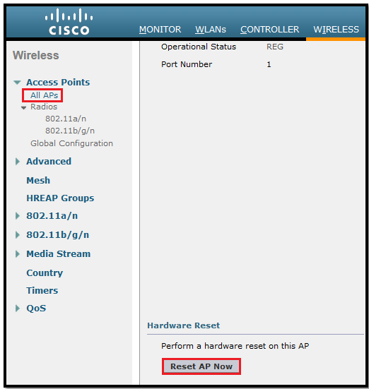
Now to remove the client form WLC1, I will reset the AP001 because we want to see if client can roam to AP002 or not with keeping the same IP.

*** But make sure that WLC must have Anchor-Foreign setup.

L3Inter2

So now our client moved to AP002.

***It is important to remember that a Layer 3 mobility event occurs only when the interface assigned to the WLAN between the controllers is not the same. Whether or not the management interfaces of each controller are in the same subnet has no bearing on a client Layer 3 roaming event.

In a Layer 3 roaming scenario, traffic returning to the wireless client goes through the anchor WLC. The anchor WLC establishes an Ethernet-over-IP (EoIP) tunnel to forward client traffic to the foreign WLC where it is then delivered to the client. All traffic originated by the client is forwarded out the corresponding VLAN interface to which the WLAN is mapped to at foreign WLC. The client’s original IP address and default gateway IP (MAC) address remain the same. All traffic, other than that which is destined for the local subnet, is forwarded to the default router where the foreign WLC substitutes the client’s default gateway MAC address with the MAC address of the default gateway associated with dynamic interface/VLAN at the foreign controller.

The following occurs when a client roams across a Layer 3 boundary:

  1. The client begins with a connection to AP001 on WLC 1.
  2. This creates an ANCHORentry in WLC 1’s client database.
  3. As the client moves away from AP001 and begins association with AP002, WLC 2 sends a mobility announcement to its peers in the mobility group looking for the WLC with information for the client MAC address.
  4. WLC 1 responds to the announcement, handshakes, and ACKs.
  5. The client database entry for the roaming client is copied to WLC 2, and marked as FOREIGN.
  6. A simple key exchange is made between the client and AP, the client is added to WLC 2’s database, which is similar to the anchor controller’s entry, except that the client entry is marked as FOREIGN.
  7. Data being sent to the WLAN client is now EoIP tunneled from the anchor WLC to the foreign WLC.
  8. Data sent by the WLAN client is sent out a local interface VLAN at the foreign controller.

***It is important to remember that a Layer 3 mobility event occurs only when the interface assigned to the WLAN between the controllers is not the same. Whether or not the management interfaces of each controller are in the same subnet has no bearing on a client Layer 3 roaming event

Once client moved, we see entry in WLC1 & marked as “Anchor”

(WLC1) >show client summary
 Number of Clients................................ 1
 MAC Address       AP Name           Status        WLAN           Auth Protocol         Port Wired
 ----------------- ----------------- ------------- -------------- ---- ---------------- ---- -----
 ab:26:96:3e:4b:ee 10.99.82.1        Associated    8              Yes  Mobile           1    N/A
(WLC1) >show client detail ab:26:96:3e:4b:ee
 Client MAC Address............................... ab:26:96:3e:4b:ee
 Client Username ................................. N/A
 AP MAC Address................................... 00:00:00:00:00:00
 AP Name.......................................... N/A
 Client State..................................... Associated
 Client NAC OOB State............................. Access
 Wireless LAN Id.................................. 8
 BSSID............................................ 00:00:00:00:00:07
 Connected For ................................... 140 secs
 Channel.......................................... N/A
 IP Address....................................... 10.99.81.40
 Association Id................................... 0
 Authentication Algorithm......................... Open System
 Reason Code...................................... 1
 Status Code...................................... 0
 Session Timeout.................................. 0
 Client CCX version............................... No CCX support
 QoS Level........................................ Silver
 802.1P Priority Tag.............................. disabled
 WMM Support...................................... Enabled
 Power Save....................................... OFF
 Supported Rates.................................. 6.0,9.0,12.0,18.0,24.0,36.0,48.0,54.0
 Mobility State................................... Anchor
 Mobility Foreign IP Address...................... 10.99.82.1
 Mobility Move Count.............................. 0
 Security Policy Completed........................ Yes
 Policy Manager State............................. RUN
 Policy Manager Rule Created...................... Yes
 ACL Name......................................... none
 ACL Applied Status............................... Unavailable
 Policy Type...................................... WPA2
 Authentication Key Management.................... PSK
 Encryption Cipher................................ CCMP (AES)
 Management Frame Protection...................... No
 EAP Type......................................... Unknown
 Interface........................................ intanchor
 VLAN............................................. 81
 Quarantine VLAN.................................. 0
 Access VLAN...................................... 81
 Client Capabilities:
 .
 .
 (WLC1) >


Check the client entry as Foreign on WLC2:

(WLC2) >show client summary
 Number of Clients................................ 1
 MAC Address       AP Name           Status        WLAN           Auth Protocol         Port Wired
 ----------------- ----------------- ------------- -------------- ---- ---------------- ---- -----
 ab:26:96:3e:4b:ee AP002            Associated    8              Yes  802.11g          1    N/A
(WLC2) >show client detail ab:26:96:3e:4b:ee
 Client MAC Address............................... ab:26:96:3e:4b:ee
 Client Username ................................. N/A
 AP MAC Address................................... 00:3a:99:14:13:70
 AP Name.......................................... AP002
 Client State..................................... Associated
 Client NAC OOB State............................. Access
 Wireless LAN Id.................................. 8
 BSSID............................................ 00:3a:99:14:13:77
 Connected For ................................... 8 secs
 Channel.......................................... 1
 IP Address....................................... 10.99.81.40
 Association Id................................... 1
 Authentication Algorithm......................... Open System
 Reason Code...................................... 1
 Status Code...................................... 0
 Session Timeout.................................. 0
 Client CCX version............................... No CCX support
 QoS Level........................................ Silver
 802.1P Priority Tag.............................. disabled
 WMM Support...................................... Enabled
 Power Save....................................... OFF
 Supported Rates.................................. 1.0,2.0,5.5,11.0,6.0,9.0,12.0,18.0,24.0,36.0,48.0,54.0
 Mobility State................................... Foreign
 Mobility Anchor IP Address....................... 10.99.80.1
 Mobility Move Count.............................. 1
 Security Policy Completed........................ Yes
 Policy Manager State............................. RUN
 Policy Manager Rule Created...................... Yes
 ACL Name......................................... none
 ACL Applied Status............................... Unavailable
 Policy Type...................................... WPA2
 Authentication Key Management.................... PSK
 Encryption Cipher................................ CCMP (AES)
 Management Frame Protection...................... No
 EAP Type......................................... Unknown
 Interface........................................ intforeign
 VLAN............................................. 84
 Quarantine VLAN.................................. 0
 Access VLAN...................................... 81
 Client Capabilities:
 .
 .
 (WLC2) >

 Basic Workflow for Inter Subnet Roaming:

L3 - Inter Controller Roaming

L3Inter3

Asymmetric Tunneling

 To know more about handoff we must see the logs from both WLC:

 Handoff logs from WLC1:

(WLC1) > debug mobility handoff enable
 (WLC1) >*mmListen: Jul 09 09:21:21.315: ab:26:96:3e:4b:ee Mobility packet received from:
 *mmListen: Jul 09 09:21:21.315: ab:26:96:3e:4b:ee   10.99.82.1, port 16666
 *mmListen: Jul 09 09:21:21.316: ab:26:96:3e:4b:ee   type: 3(MobileAnnounce)  subtype: 0  version: 1  xid: 25  seq: 101  len 116 flags 0
 *mmListen: Jul 09 09:21:21.316: ab:26:96:3e:4b:ee   group id: d7f8a4f2 cb038b78 641818bb a26869b4
 *mmListen: Jul 09 09:21:21.316: ab:26:96:3e:4b:ee   mobile MAC: ab:26:96:3e:4b:ee, IP: 0.0.0.0, instance: 0
 *mmListen: Jul 09 09:21:21.316: ab:26:96:3e:4b:ee   VLAN IP: 10.99.84.3, netmask: 255.255.255.0
 *mmListen: Jul 09 09:21:21.316: Switch IP: 10.99.82.1
 *mmListen: Jul 09 09:21:21.316: Vlan List payload not found, ignoring ...
 *mmListen: Jul 09 09:21:21.316: IP Address don't compare for client ab:26:96:3e:4b:ee is 0
 *mmListen: Jul 09 09:21:21.316: ab:26:96:3e:4b:ee Handoff as Local, Client IP: 10.99.81.40 Anchor IP: 10.99.80.1
 *mmListen: Jul 09 09:21:21.316: Anchor Mac : 00.21.d8.fa.66.00
 *mmListen: Jul 09 09:21:21.316: ab:26:96:3e:4b:ee Mobility packet sent to:
 *mmListen: Jul 09 09:21:21.316: ab:26:96:3e:4b:ee   10.99.82.1, port 16666
 *mmListen: Jul 09 09:21:21.316: ab:26:96:3e:4b:ee   type: 5(MobileHandoff)  subtype: 0  version: 1  xid: 25  seq: 132  len 546 flags 0
 *mmListen: Jul 09 09:21:21.316: ab:26:96:3e:4b:ee   group id: d7f8a4f2 cb038b78 641818bb a26869b4
 *mmListen: Jul 09 09:21:21.316: ab:26:96:3e:4b:ee   mobile MAC: ab:26:96:3e:4b:ee, IP: 10.99.81.40, instance: 0
 *mmListen: Jul 09 09:21:21.316: ab:26:96:3e:4b:ee   VLAN IP: 10.99.81.1, netmask: 255.255.255.0
 *apfReceiveTask: Jul 09 09:21:21.316: ab:26:96:3e:4b:ee 10.99.81.40 RUN (20) mobility role update request from Local to Anchor Peer = 10.99.82.1, Old Anchor = 10.99.80.1, New Anchor = 10.99.80.1
 *apfReceiveTask: Jul 09 09:21:21.318: ab:26:96:3e:4b:ee 10.99.81.40 RUN (20) Plumbing duplex mobility tunnel to 10.99.82.1 as Anchor (VLAN 81)
 *apfReceiveTask: Jul 09 09:21:21.318: ab:26:96:3e:4b:ee Mobility Response: IP 10.99.81.40 code Handoff Indication (2), reason Client handoff successful - anchor released (1), PEM State RUN, Role Anchor(2)

Handoff logs from WLC2:

(WLC2) >debug mobility handoff enable
 (WLC2) >*Dot1x_NW_MsgTask_0: Jul 09 09:39:02.572: ab:26:96:3e:4b:ee Mobility query, PEM State: L2AUTHCOMPLETE
 *Dot1x_NW_MsgTask_0: Jul 09 09:39:02.573: ab:26:96:3e:4b:ee Mobility packet sent to:
 *Dot1x_NW_MsgTask_0: Jul 09 09:39:02.573: ab:26:96:3e:4b:ee   10.99.80.1, port 16666
 *Dot1x_NW_MsgTask_0: Jul 09 09:39:02.573: ab:26:96:3e:4b:ee   type: 3(MobileAnnounce)  subtype: 0  version: 1  xid: 22  seq: 89  len 116 flags 0
 *Dot1x_NW_MsgTask_0: Jul 09 09:39:02.573: ab:26:96:3e:4b:ee   group id: d7f8a4f2 cb038b78 641818bb a26869b4
 *Dot1x_NW_MsgTask_0: Jul 09 09:39:02.573: ab:26:96:3e:4b:ee   mobile MAC: ab:26:96:3e:4b:ee, IP: 0.0.0.0, instance: 0
 *Dot1x_NW_MsgTask_0: Jul 09 09:39:02.574: ab:26:96:3e:4b:ee   VLAN IP: 10.99.84.3, netmask: 255.255.255.0
 *mmListen: Jul 09 09:39:02.575: ab:26:96:3e:4b:ee Mobility packet received from:
 *mmListen: Jul 09 09:39:02.575: ab:26:96:3e:4b:ee   10.99.80.1, port 16666
 *mmListen: Jul 09 09:39:02.575: ab:26:96:3e:4b:ee   type: 5(MobileHandoff)  subtype: 0  version: 1  xid: 22  seq: 118  len 546 flags 0
 *mmListen: Jul 09 09:39:02.575: ab:26:96:3e:4b:ee   group id: d7f8a4f2 cb038b78 641818bb a26869b4
 *mmListen: Jul 09 09:39:02.575: ab:26:96:3e:4b:ee   mobile MAC: ab:26:96:3e:4b:ee, IP: 10.99.81.40, instance: 0
 *mmListen: Jul 09 09:39:02.575: ab:26:96:3e:4b:ee   VLAN IP: 10.99.81.1, netmask: 255.255.255.0
 *mmListen: Jul 09 09:39:02.575: Switch IP: 10.99.80.1
 *mmListen: Jul 09 09:39:02.575: Mobility handoff, NAC State Payload [ Client's NAC OOB State : Access, Quarantine VLAN :0, Access VLAN : 81 ]
 *mmListen: Jul 09 09:39:02.575: ab:26:96:3e:4b:ee Mobility handoff for client:Ip: 10.99.81.40 Anchor IP: 10.99.80.1, Peer IP: 10.99.80.1
 *apfReceiveTask: Jul 09 09:39:02.579: ab:26:96:3e:4b:ee Handoff confirm: Pre Handoff PEM State: RUN
 *apfReceiveTask: Jul 09 09:39:02.579: ab:26:96:3e:4b:ee   Pem State update: RUN(20), VAP Security mask 40004000,        IPsec len: 0, ACL Name: ''
 *apfReceiveTask: Jul 09 09:39:02.581: ab:26:96:3e:4b:ee 10.99.81.40 RUN (20) mobility role update request from Unassociated to Foreign Peer = 10.99.80.1, Old Anchor = 10.99.80.1, New Anchor = 10.99.80.1
 *apfReceiveTask: Jul 09 09:39:02.583: ab:26:96:3e:4b:ee 10.99.81.40 RUN (20) Plumbing duplex mobility tunnel to 10.99.80.1 as Foreign, (VLAN 84)
 *apfReceiveTask: Jul 09 09:39:02.583: ab:26:96:3e:4b:ee Configured Anchor for mobile ab:26:96:3e:4b:ee. Sending Igmp query
 *apfReceiveTask: Jul 09 09:39:02.583: ab:26:96:3e:4b:ee Mobility Response: IP 10.99.81.40 code Handoff (1), reason Handoff success (0), PEM State RUN, Role Foreign(3)
 *bcastReceiveTask: Jul 09 09:39:02.598: Sending IGMP query First Time to 00:3a:99:14:13:70 ap for mgid 5
 *bcastReceiveTask: Jul 09 09:39:02.598: Entry for ap  00:3a:99:14:13:70, IGMP query packet not queued for mgid 5... Enquing the Query packet...
 *bcastReceiveTask: Jul 09 09:39:03.456: Sending IGMP query to 00:3a:99:14:13:70 ap for mgid 5, Query count: 2
 *bcastReceiveTask: Jul 09 09:39:04.456: Sending IGMP query to 00:3a:99:14:13:70 ap for mgid 5, Query count: 1

Layer2- Inter Controller Roaming

In this post we will see the roaming between inter controllers.

Inter-controller roaming occurs when a client roams between two APs registered to two different controllers, where each controller has an interface in the client subnet. When a client roams between controllers on the same subnet, the controllers exchange mobility messages, and the client database entry is transferred from the original controller to the new controller. Client traffic then flows through the new controller on to the network just like it did on the original controller.

My Topology

L2Inter1

Basic Workflow of inter controller roaming:

L2 - Inter Controller Roaming

L2Inter2

My client already connected to WLC1: See the output from WLC1

(WLC1) >show client summary
 Number of Clients................................ 1
 MAC Address       AP Name           Status        WLAN           Auth Protocol         Port Wired
 ----------------- ----------------- ------------- -------------- ---- ---------------- ---- -----
 ab:26:96:3e:4b:ee AP001             Associated    8              Yes   802.11a          1    N/A
(WLC1) >show client detail ab:26:96:3e:4b:ee
 Client MAC Address............................... ab:26:96:3e:4b:ee
 Client Username ................................. N/A
 AP MAC Address................................... 00:22:bd:98:3a:30
 AP Name.......................................... AP001
 Client State..................................... Associated
 Client NAC OOB State............................. Access
 Wireless LAN Id.................................. 8
 BSSID............................................ 00:22:bd:98:3a:38
 Connected For ................................... 12 secs
 Channel.......................................... 36
 IP Address....................................... 10.99.81.22
 Association Id................................... 1
 Authentication Algorithm......................... Open System
 Reason Code...................................... 1
 Status Code...................................... 0
 Session Timeout.................................. 0
 Client CCX version............................... No CCX support
 QoS Level........................................ Silver
 802.1P Priority Tag.............................. disabled
 WMM Support...................................... Enabled
 Power Save....................................... OFF
 Supported Rates.................................. 6.0,9.0,12.0,18.0,24.0,36.0,48.0,54.0
 Mobility State................................... Local
 Mobility Move Count.............................. 0
 Security Policy Completed........................ Yes
 Policy Manager State............................. RUN
 Policy Manager Rule Created...................... Yes
 ACL Name......................................... none
 ACL Applied Status............................... Unavailable
 Policy Type...................................... WPA2
 Authentication Key Management.................... PSK
 Encryption Cipher................................ CCMP (AES)
 Management Frame Protection...................... No
 EAP Type......................................... Unknown
 Interface........................................ interwlc
 VLAN............................................. 81
 Quarantine VLAN.................................. 0
 Access VLAN...................................... 81
 Client Capabilities:
 .
 .
 .
 (WLC1) >
  

Now I will reset AP001 to disconnect my client forcefully to check the roaming.

Go to Wireless > All AP and then click on AP001 > Reset AP Now.

L2Inter3

Once AP001 will reset after that our client will roam to another AP(AP002).

See the logs for client which moved to WLC2.

(WLC2) >show client summary
 Number of Clients................................ 1
 MAC Address       AP Name           Status        WLAN           Auth Protocol         Port Wired
 ----------------- ----------------- ------------- -------------- ---- ---------------- ---- -----
 ab:26:96:3e:4b:ee AP002             Associated    8              Yes  802.11g          1    N/A
(99CWLAN2) >show client detail ab:26:96:3e:4b:ee
 Client MAC Address............................... ab:26:96:3e:4b:ee
 Client Username ................................. N/A
 AP MAC Address................................... 00:3a:99:14:13:70
 AP Name.......................................... AP002
 Client State..................................... Associated
 Client NAC OOB State............................. Access
 Wireless LAN Id.................................. 8
 BSSID............................................ 00:3a:99:14:13:77
 Connected For ................................... 21 secs
 Channel.......................................... 1
 IP Address....................................... 10.99.81.22
 Association Id................................... 1
 Authentication Algorithm......................... Open System
 Reason Code...................................... 1
 Status Code...................................... 0
 Session Timeout.................................. 0
 Client CCX version............................... No CCX support
 QoS Level........................................ Silver
 802.1P Priority Tag.............................. disabled
 WMM Support...................................... Enabled
 Power Save....................................... OFF
 Supported Rates.................................. 1.0,2.0,5.5,11.0,6.0,9.0,12.0,18.0,24.0,36.0,48.0,54.0
 Mobility State................................... Local
 Mobility Move Count.............................. 0
 Security Policy Completed........................ Yes
 Policy Manager State............................. RUN
 Policy Manager Rule Created...................... Yes
 ACL Name......................................... none
 ACL Applied Status............................... Unavailable
 Policy Type...................................... WPA2
 Authentication Key Management.................... PSK
 Encryption Cipher................................ CCMP (AES)
 Management Frame Protection...................... No
 EAP Type......................................... Unknown
 Interface........................................ interwlc
 VLAN............................................. 81
 Quarantine VLAN.................................. 0
 Access VLAN...................................... 81
 Client Capabilities:
 .
 .
 (WLC2) >


Intra-Controller Roaming

If a client roams between APs on the same controller, it is called an intra-controller mobility event. Intra-controller roaming is the most simplistic in that all the controller needs to do is update the database with the AP association and establish new security contexts if necessary. Basically, the Layer 3–related mobility is handled by the controller, and the link layer mobility is handled by the AP. As the client roams, the controller updates the client state. The client traffic then flows through the new AP LWAPP/CAPWAP tunnel to the controller and out on the network. Figure 9-1 illustrates an intra-controller roam

Intra Controller Roaming

I will not go in details for these because it is the simplest Roaming 🙂

More info about Roaming, please visit this post: Mobility Basics

Mobility Configuring on WLC

In this post we will learn how to configure WLC mobility on Cisco Controllers.

Mobility, or roaming, is a wireless LAN client’s ability to maintain its association seamlessly from one access point to another securely and with as little latency as possible.

More Info about Mobility/Roamin please visit This Section : Mobility Basics

A mobility group is a set of controllers, identified by the same mobility group name that make seamless roaming for wireless clients. By creating a mobility group, we can enable multiple controllers in a network to dynamically share information and forward data traffic when inter-controller or inter-subnet roaming occurs. Controllers in the same mobility group can share the context and state of client devices as well as their list of access points so that they do not consider each other’s access points as rogue devices.

First of All we need to configure Mobility Group name on each controller while setting up (Initial Config) the controller.

Virtual Gateway IP Address: 1.1.1.1
Multicast IP Address: 239.255.255.1 / 3
Mobility/RF Group Name: Test
Network Name (SSID): Test
 

Via GUI:

To add an entry to a controller mobility configuration using the GUI, go to CONTROLLER > Mobility Management > Mobility Groups and click on New.

Untitled


Here we enter the MAC address and IP address of the controller management interface we are adding along with the mobility group name of that controller.

In WLC1 we will add WLC2 mac and IP address.
In WLC2 we will add WLC1 mac and IP address.

Here I will posts the screenshot from WLC1, we also need to add same in WLC2.

Untitled


Once we add the WLC MAC & management interface IP address the status will shows us as UP (Be aware sometime it take 20-30 seconds):

Untitled


Note: For controllers to be in the same mobility group, they need to meet the following criteria:

Identical mobility group names: The mobility group name is case sensitive. A mobility group name of ABC is not the same as abc from the controller perspective.

Same virtual interface IP address: If the virtual IPs are not the same between the controllers, the handoff of the client database entry will not take place and the client will be disconnected for a short period.

Same version of code: This is true for supporting normal client mobility. Starting with the 5.2 release, a 5.2 or 6.0 controller supports auto-anchoring with 4.2 and higher code running on the anchor controller.

Network connectivity between the controller in the mobility group: We should be able to mping and eping between the controllers. These special pings will be discussed in other post.

Remembering points in brief before configuring Mobility:

  • IP connectivity must exist between the management interfaces of all controllers.
  • All controllers must be configured with the same mobility group name.
  • All controllers must be configured with the same virtual interface IP address.
  • We must have gathered the MAC address and IP address of every controller that is to be included in the mobility group. This information is necessary because we will be configuring all controllers with the MAC address and IP address of all the other mobility group members.
  • When we configure mobility groups using a firewall, for example, Cisco ASA, we must open port 16666, and IP protocol 97.

We have only 2 WLC so we will not configure Multicast Group IP address in this post.

If we have multiple controllers in Mobility Group then we must configure Multicast Group IP address on each controller.

Mobility4

Via CLI:

config mobility group domain domain_name

(WLC1) > config mobility group domain Test

config mobility group member add mac_address ip_address

(WLC1) > config mobility group member add 00:21:d8:fa:fd:a0 192.168.82.1

config mobility multicast-mode {enable | disable} local_group_multicast_address

(WLC1) > config mobility multicast-mode enable 239.255.255.254

config mobility group multicast-address group_name IP_address

(WLC1) > config mobility group multicast-address Test 239.255.255.254

See the verification of Mobility Summary by using this command:

Show mobility Summary

(WLC1) >show mobility summary
 Symmetric Mobility Tunneling (current) .......... Enabled
 Symmetric Mobility Tunneling (after reboot) ..... Enabled
 Mobility Protocol Port........................... 16666
 Default Mobility Domain.......................... Test
 Multicast Mode .................................. Disabled
 Mobility Domain ID for 802.11r................... 0x840e
 Mobility Keepalive Interval...................... 10
 Mobility Keepalive Count......................... 3
 Mobility Group Members Configured................ 2
 Mobility Control Message DSCP Value.............. 0
 Controllers configured in the Mobility Group
 MAC Address        IP Address       Group Name                        Multicast IP     Status
 00:21:d8:fa:66:00  192.168.80.1       Test                              0.0.0.0          Up
 00:21:d8:fa:fd:a0  192.168.82.1       Test                              0.0.0.0          Up
 (WLC1) >